D12363VTE33 Renesas Electronics America, D12363VTE33 Datasheet - Page 681
D12363VTE33
Manufacturer Part Number
D12363VTE33
Description
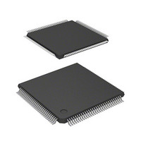
MCU 3V 0K 120-TQFP
Manufacturer
Renesas Electronics America
Series
H8® H8S/2300r
Datasheet
1.DF2368VTE34V.pdf
(1044 pages)
Specifications of D12363VTE33
Core Processor
H8S/2000
Core Size
16-Bit
Speed
33MHz
Connectivity
I²C, IrDA, SCI, SmartCard
Peripherals
DMA, POR, PWM, WDT
Number Of I /o
84
Program Memory Type
ROMless
Ram Size
16K x 8
Voltage - Supply (vcc/vdd)
3 V ~ 3.6 V
Data Converters
A/D 10x10b, D/A 2x8b
Oscillator Type
Internal
Operating Temperature
-20°C ~ 75°C
Package / Case
120-TQFP, 120-VQFP
Lead Free Status / RoHS Status
Contains lead / RoHS non-compliant
Eeprom Size
-
Program Memory Size
-
Other names
HD6412363VTE33
HD6412363VTE33
HD6412363VTE33
Available stocks
Company
Part Number
Manufacturer
Quantity
Price
Company:

Part Number:
D12363VTE33V
Manufacturer:
Renesas Electronics America
Quantity:
10 000


14.9.2
Table 14.14 shows the interrupt sources in Smart Card interface mode. The transmit end interrupt
(TEI) request cannot be used in this mode.
Table 14.14 Interrupt Sources
In Smart Card interface mode, as in normal serial communication interface mode, transfer can be
carried out using the DTC or DMAC. In transmit operations, the TDRE flag is also set to 1 at the
same time as the TEND flag in SSR, and a TXI interrupt is generated. If the TXI request is
designated beforehand as a DTC or DMAC activation source, the DTC or DMAC will be
activated by the TXI request, and transfer of the transmit data will be carried out. The TDRE and
TEND flags are automatically cleared to 0 when data transfer is performed by the DTC or DMAC.
In the event of an error, the SCI retransmits the same data automatically. During this period, the
TEND flag remains cleared to 0 and the DTC or DMAC is not activated. Therefore, the SCI and
DTC or DMAC will automatically transmit the specified number of bytes in the event of an error,
including retransmission. However, the ERS flag is not cleared automatically when an error
occurs, and so the RIE bit should be set to 1 beforehand so that an ERI request will be generated in
the event of an error, and the ERS flag will be cleared.
Channel
0
1
2
3
4
Interrupts in Smart Card Interface Mode
Name
ERI0
RXI0
TXI0
ERI1
RXI1
TXI1
ERI2
RXI2
TXI2
ERI3
RXI3
TXI3
ERI4
RXI4
TXI4
Interrupt Source
Receive Error, detection
Receive Data Full
Transmit Data Empty
Receive Error, detection
Receive Data Full
Transmit Data Empty
Receive Error, detection
Receive Data Full
Transmit Data Empty
Receive Error, detection
Receive Data Full
Transmit Data Empty
Receive Error, detection
Receive Data Full
Transmit Data Empty
Interrupt Flag
ORER, PER, ERS
RDRF
TEND
ORER, PER, ERS
RDRF
TEND
ORER, PER, ERS
RDRF
TEND
ORER, PER, ERS
RDRF
TEND
ORER, PER, ERS
RDRF
TEND
Section 14 Serial Communication Interface (SCI, IrDA)
Rev.6.00 Mar. 18, 2009 Page 621 of 980
DTC
Activation
Not possible
Possible
Possible
Not possible
Possible
Possible
Not possible
Possible
Possible
Not possible
Possible
Possible
Not possible
Possible
Possible
DMAC
Activation
Not possible
Possible
Possible
Not possible
Possible
Possible
Not possible
Not possible
Not possible
Not possible
Not possible
Not possible
Not possible
Not possible
Not possible
REJ09B0050-0600
Priority
High
Low
Related parts for D12363VTE33
Image
Part Number
Description
Manufacturer
Datasheet
Request
R

Part Number:
Description:
KIT STARTER FOR M16C/29
Manufacturer:
Renesas Electronics America
Datasheet:

Part Number:
Description:
KIT STARTER FOR R8C/2D
Manufacturer:
Renesas Electronics America
Datasheet:

Part Number:
Description:
R0K33062P STARTER KIT
Manufacturer:
Renesas Electronics America
Datasheet:

Part Number:
Description:
KIT STARTER FOR R8C/23 E8A
Manufacturer:
Renesas Electronics America
Datasheet:

Part Number:
Description:
KIT STARTER FOR R8C/25
Manufacturer:
Renesas Electronics America
Datasheet:

Part Number:
Description:
KIT STARTER H8S2456 SHARPE DSPLY
Manufacturer:
Renesas Electronics America
Datasheet:

Part Number:
Description:
KIT STARTER FOR R8C38C
Manufacturer:
Renesas Electronics America
Datasheet:

Part Number:
Description:
KIT STARTER FOR R8C35C
Manufacturer:
Renesas Electronics America
Datasheet:

Part Number:
Description:
KIT STARTER FOR R8CL3AC+LCD APPS
Manufacturer:
Renesas Electronics America
Datasheet:
Part Number:
Description:
KIT STARTER FOR RX610
Manufacturer:
Renesas Electronics America
Datasheet:

Part Number:
Description:
KIT STARTER FOR R32C/118
Manufacturer:
Renesas Electronics America
Datasheet:

Part Number:
Description:
KIT DEV RSK-R8C/26-29
Manufacturer:
Renesas Electronics America
Datasheet:

Part Number:
Description:
KIT STARTER FOR SH7124
Manufacturer:
Renesas Electronics America
Datasheet:

Part Number:
Description:
KIT STARTER FOR H8SX/1622
Manufacturer:
Renesas Electronics America
Datasheet:

Part Number:
Description:
KIT DEV FOR SH7203
Manufacturer:
Renesas Electronics America
Datasheet: