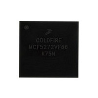
MCF5272VF66 Freescale, MCF5272VF66 Datasheet - Page 277

MCF5272VF66
Manufacturer Part Number
MCF5272VF66
Description
Manufacturer
Freescale
Datasheet
1.MCF5272VF66.pdf
(544 pages)
Specifications of MCF5272VF66
Family Name
MCF5xxx
Device Core
ColdFire
Device Core Size
32b
Frequency (max)
66MHz
Instruction Set Architecture
RISC
Supply Voltage 1 (typ)
3.3V
Operating Temp Range
0C to 70C
Operating Temperature Classification
Commercial
Mounting
Surface Mount
Pin Count
196
Package Type
MA-BGA
Lead Free Status / RoHS Status
Not Compliant
Available stocks
Company
Part Number
Manufacturer
Quantity
Price
Company:
Part Number:
MCF5272VF66
Manufacturer:
HYNIX
Quantity:
19
Company:
Part Number:
MCF5272VF66
Manufacturer:
FREESCAL
Quantity:
885
Company:
Part Number:
MCF5272VF66
Manufacturer:
Freescale Semiconductor
Quantity:
10 000
Part Number:
MCF5272VF66
Manufacturer:
FREESCALE
Quantity:
20 000
Company:
Part Number:
MCF5272VF66J
Manufacturer:
Freescale
Quantity:
256
Company:
Part Number:
MCF5272VF66J
Manufacturer:
Freescale Semiconductor
Quantity:
10 000
Company:
Part Number:
MCF5272VF66R2
Manufacturer:
Freescale Semiconductor
Quantity:
10 000
Company:
Part Number:
MCF5272VF66R2J
Manufacturer:
Freescale Semiconductor
Quantity:
10 000
- Current page: 277 of 544
- Download datasheet (7Mb)
Freescale Semiconductor
Bits
5–4
3–2
7
6
1
0
CRC_ERR
OUT_LVL
IN_DONE
IN_LVL
Name
—
—
MCF5272 ColdFire
CRC error generation enable. This bit enables CRC error generation for debug and test purpose.
In order to use this feature, the DEBUG bit must be set. Enabling this bit causes a CRC error on
the next data packet transmitted. The CRC_ERR bit must be set again in order to generate
another CRC error. This bit only applies to IN transfers. This command bit is write-only and always
returns 0 when read.
1 CRC error generation if DEBUG = 1
0 default value
Reserved, should be cleared.
Endpoint 0 OUT FIFO level for interrupt. This field selects the FIFO level to generate an OUT_LVL
interrupt. The OUT_LVL interrupt is generated when the FIFO fills above the selected level.
00 FIFO 25% Full
01 FIFO
10 FIFO
11 FIFO 100% Full
Endpoint 0 IN FIFO level for interrupt. This field selects the FIFO level to generate an IN_LVL
interrupt. The IN_LVL interrupt is generated when the FIFO falls below the selected level.
00 FIFO 25% Empty
01 FIFO
10 FIFO
11 FIFO 100% Empty
This bit controls the USB's response to IN tokens from the host. This bit is set at Reset and must
be cleared by software when the last byte of a transfer has been written to the IN-FIFO. This bit is
then subsequently set by the USB core when an end of transfer (EOT) event occurs indicating that
the transfer has been completed. An end of transfer (EOT) event is indicated by one of the
following:
a) An IN packet is transmitted that contains less than the maximum number of bytes defined at
b) A zero length IN packet is transmitted. This occurs when the previously transmitted IN packet
0 CPU has completed writing to the IN-FIFO and transfer is in progress. The USB module will
1 Transfer completed or CPU Busy writing transfer into the IN-FIFO. The USB module will only
Reserved, should be cleared.
send any amount of data in the FIFO or a zero-length packet when the FIFO is empty.
send maximum size packets or NAK responses if the FIFO contains less than a maximum size
packet. This bit is set at Reset and on an EOT event.
Table 12-12. EP0CTL Field Descriptions (continued)
endpoint configuration.
was full, and no more data remains in the IN-FIFO. Hence a single zero length packet must be
sent to indicate EOT.
50%
75%
50%
75%
Full
Empty
Full
Empty
®
Integrated Microprocessor User’s Manual, Rev. 3
Description
Universal Serial Bus (USB)
12-19
Related parts for MCF5272VF66
Image
Part Number
Description
Manufacturer
Datasheet
Request
R
Part Number:
Description:
Mcf5272 Coldfire Integrated Microprocessor User
Manufacturer:
Freescale Semiconductor, Inc
Datasheet:

Part Number:
Description:
MCF5272 Interrupt Service Routine for the Physical Layer Interface Controller
Manufacturer:
Freescale Semiconductor / Motorola
Datasheet:

Part Number:
Description:
TOWER ELEVATOR BOARDS HARDWARE
Manufacturer:
Freescale Semiconductor
Datasheet:

Part Number:
Description:
TOWER SERIAL I/O HARDWARE
Manufacturer:
Freescale Semiconductor
Datasheet:

Part Number:
Description:
LCD MODULE FOR TWR SYSTEM
Manufacturer:
Freescale Semiconductor
Datasheet:

Part Number:
Description:
DAUGHTER LCD WVGA I.MX51
Manufacturer:
Freescale Semiconductor
Datasheet:

Part Number:
Description:
TOWER SYSTEM BOARD MPC5125
Manufacturer:
Freescale Semiconductor
Datasheet:

Part Number:
Description:
KIT EVALUATION I.MX51
Manufacturer:
Freescale Semiconductor
Datasheet:

Part Number:
Description:
KIT DEVELOPMENT WINCE IMX25
Manufacturer:
Freescale Semiconductor
Datasheet:

Part Number:
Description:
TOWER SYSTEM KIT MPC5125
Manufacturer:
Freescale Semiconductor
Datasheet:

Part Number:
Description:
TOWER SYSTEM BOARD K40X256
Manufacturer:
Freescale Semiconductor
Datasheet:

Part Number:
Description:
TOWER SYSTEM KIT K40X256
Manufacturer:
Freescale Semiconductor
Datasheet:

Part Number:
Description:
Microcontrollers (MCU) MX28 PLATFORM DEV KIT
Manufacturer:
Freescale Semiconductor
Datasheet:

Part Number:
Description:
MCU, MPU & DSP Development Tools IAR KickStart Kit for Kinetis K60
Manufacturer:
Freescale Semiconductor
Datasheet:

Part Number:
Description:
24BIT HDMI MX535/08
Manufacturer:
Freescale Semiconductor
Datasheet:


