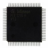
PEB2255H-V13 Infineon Technologies, PEB2255H-V13 Datasheet - Page 144

PEB2255H-V13
Manufacturer Part Number
PEB2255H-V13
Description
IC INTERFACE LINE 80-MQFP
Manufacturer
Infineon Technologies
Datasheet
1.PEB2255H-V13.pdf
(374 pages)
Specifications of PEB2255H-V13
Applications
*
Interface
*
Voltage - Supply
*
Package / Case
80-SQFP
Mounting Type
Surface Mount
Lead Free Status / RoHS Status
Lead free / RoHS Compliant
Other names
PEB2255H-V13
PEB2255H-V13IN
PEB2255H-V13IN
Available stocks
Company
Part Number
Manufacturer
Quantity
Price
Company:
Part Number:
PEB2255H-V13
Manufacturer:
Infineon Technologies
Quantity:
10 000
- Current page: 144 of 374
- Download datasheet (6Mb)
5.4.5.2
Remote alarm (yellow alarm) is indicated by the periodical pattern ‘1111 1111 0000 0000
…’ in the DL bits. Remote alarm is declared even in the presence of BER 1/1000. The
alarm is reset when the “yellow alarm pattern“ no longer is detected.
Depending on bit RC1.SJR the FALC
according to JT G. 704. In the DL-bit position 16 continuos “1“ are transmitted if
FMR0.SRAF=0 and FMR4.XRA=1.
Alternatively remote alarm can be indicated by setting bit 2 of every time slot after
selecting FMR0.SRAF = 1.
5.4.5.3
Generation and checking of CRC6 bits transmitted/received in the e1-e6 bit positions is
done according to ITU-T G.706. The CRC6 checking algorithm is enabled via bit
FMR1.CRC. If not enabled, all check bits in the transmit direction are set. In the
synchronous state received CRC6 errors are accumulated in a 16 bit error counter and
are additionally indicated by an interrupt status.
• CRC6 Inversion
If enabled by bit RC0.CRCI, all CRC bits of one outgoing extended multiframe are
automatically inverted in case a CRC error is flagged for the previous received
multiframe. Setting the bit RC0.XCRCI inverts the CRC bits before transmitted to the
distant end. This function is logically ored with RC0.CRCI.
• CRC6 Generation/Checking According to JT G. 706
Setting of RC1.SJR the FALC
JT G. 706. The CRC6 checksum is calculated including the FS/DL bits. In synchronous
state CRC6 errors increment an error counter.
5.4.6
The 72-multiframe is an alternate use of the FS-bit pattern and is used for carrying data
link information. This is done by stealing some of redundant multiframing bits after the
transmission of the 12-bit framing header (refer to
of A and B signaling channels (robbed bit signaling) is defined by zero-to-one and one-
to-zero transitions of the FS bits and is continued when the FS bits are replaced by the
data link bits.
Remote Alarm (Yellow Alarm) is indicated by setting bit 2 to zero in each time slot. An
additional use of the D bits for alarm indication is user defined and must be done
externally.
Data Sheet
Remote Alarm (yellow alarm) Generation/Detection
CRC6 Generation and Checking (T1/J1)
72-Frame Multiframe (SLC96 Format, T1/J1)
®
-LH generates and check the CRC6 bits according to
®
-LH generates and detect the Remote Alarm
144
Figure 36
Functional Description T1/J1
on page 146). The position
FALC-LH V1.3
PEB 2255
2000-07
Related parts for PEB2255H-V13
Image
Part Number
Description
Manufacturer
Datasheet
Request
R

Part Number:
Description:
E1/t1/j1 Framer And Line Interface Component For Long And Short Haul Applications
Manufacturer:
Infineon Technologies Corporation
Datasheet:

Part Number:
Description:
Manufacturer:
Infineon Technologies AG
Datasheet:

Part Number:
Description:
Manufacturer:
Infineon Technologies AG
Datasheet:

Part Number:
Description:
Manufacturer:
Infineon Technologies AG
Datasheet:

Part Number:
Description:
Manufacturer:
Infineon Technologies AG
Datasheet:

Part Number:
Description:
Manufacturer:
Infineon Technologies AG
Datasheet:

Part Number:
Description:
Manufacturer:
Infineon Technologies AG
Datasheet:

Part Number:
Description:
Manufacturer:
Infineon Technologies AG
Datasheet:

Part Number:
Description:
16-bit microcontroller with 2x2 KByte RAM
Manufacturer:
Infineon Technologies AG
Datasheet:

Part Number:
Description:
NPN silicon RF transistor
Manufacturer:
Infineon Technologies AG
Datasheet:

Part Number:
Description:
NPN silicon RF transistor
Manufacturer:
Infineon Technologies AG
Datasheet:

Part Number:
Description:
NPN silicon RF transistor
Manufacturer:
Infineon Technologies AG
Datasheet:

Part Number:
Description:
NPN silicon RF transistor
Manufacturer:
Infineon Technologies AG
Datasheet:

Part Number:
Description:
Si-MMIC-amplifier in SIEGET 25-technologie
Manufacturer:
Infineon Technologies AG
Datasheet:

Part Number:
Description:
IGBT Power Module
Manufacturer:
Infineon Technologies AG
Datasheet:


