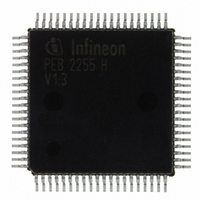
PEB2255H-V13 Infineon Technologies, PEB2255H-V13 Datasheet - Page 43

PEB2255H-V13
Manufacturer Part Number
PEB2255H-V13
Description
IC INTERFACE LINE 80-MQFP
Manufacturer
Infineon Technologies
Datasheet
1.PEB2255H-V13.pdf
(374 pages)
Specifications of PEB2255H-V13
Applications
*
Interface
*
Voltage - Supply
*
Package / Case
80-SQFP
Mounting Type
Surface Mount
Lead Free Status / RoHS Status
Lead free / RoHS Compliant
Other names
PEB2255H-V13
PEB2255H-V13IN
PEB2255H-V13IN
Available stocks
Company
Part Number
Manufacturer
Quantity
Price
Company:
Part Number:
PEB2255H-V13
Manufacturer:
Infineon Technologies
Quantity:
10 000
- Current page: 43 of 374
- Download datasheet (6Mb)
•
Table 5
Pin No.
1
5
16
14
27, 37, 74
26, 36, 73
54
Data Sheet
Symbol
V
V
V
V
V
V
RES
DDR
SSR
DDX
SSX
SS
DD
Pin Definitions - Miscellaneous
Input (I)
Output (O)
Supply (S)
S
S
S
S
S
S
I
Power Supply
Device Reset
Function
Positive Power Supply for the analog receiver
Power Supply: Ground for the analog receiver
Positive Power Supply for the analog
transmitter
Power Supply: Ground for the analog
transmitter
Power Supply: Ground for digital subcircuits
(0 V)
For correct operation, all three pins have to be
connected to ground.
Positive Power Supply
for the digital subcircuits (5.0 V)
For correct operation, all three pins have to be
connected to positive power supply.
Reset
A high signal on this pin forces the FALC
into reset state. During Reset the FALC
needs active clocks on pins SCLKR, SCLKX,
XTAL1 and XTAL3 (E1: XTAL3 only, if slicer
mode selectable by LIM1.JATT/RL = 10 will be
used).
During Reset
- all unidirectional output stages are in high-
impedance state, except pins CLK16M,
CLK12M, CLK8M, CLKX, FSC, XCLK and
RCLK (active clocks are required during reset on
pins SCLKR, SCLKX, XTAL1 and XTAL3
- all bidirectional output stages (data bus) are in
input mode if signal RD is “high”
43
Pin Descriptions
FALC-LH V1.3
PEB 2255
®
-LH
®
1)
2000-07
-LH
)
Related parts for PEB2255H-V13
Image
Part Number
Description
Manufacturer
Datasheet
Request
R

Part Number:
Description:
E1/t1/j1 Framer And Line Interface Component For Long And Short Haul Applications
Manufacturer:
Infineon Technologies Corporation
Datasheet:

Part Number:
Description:
Manufacturer:
Infineon Technologies AG
Datasheet:

Part Number:
Description:
Manufacturer:
Infineon Technologies AG
Datasheet:

Part Number:
Description:
Manufacturer:
Infineon Technologies AG
Datasheet:

Part Number:
Description:
Manufacturer:
Infineon Technologies AG
Datasheet:

Part Number:
Description:
Manufacturer:
Infineon Technologies AG
Datasheet:

Part Number:
Description:
Manufacturer:
Infineon Technologies AG
Datasheet:

Part Number:
Description:
Manufacturer:
Infineon Technologies AG
Datasheet:

Part Number:
Description:
16-bit microcontroller with 2x2 KByte RAM
Manufacturer:
Infineon Technologies AG
Datasheet:

Part Number:
Description:
NPN silicon RF transistor
Manufacturer:
Infineon Technologies AG
Datasheet:

Part Number:
Description:
NPN silicon RF transistor
Manufacturer:
Infineon Technologies AG
Datasheet:

Part Number:
Description:
NPN silicon RF transistor
Manufacturer:
Infineon Technologies AG
Datasheet:

Part Number:
Description:
NPN silicon RF transistor
Manufacturer:
Infineon Technologies AG
Datasheet:

Part Number:
Description:
Si-MMIC-amplifier in SIEGET 25-technologie
Manufacturer:
Infineon Technologies AG
Datasheet:

Part Number:
Description:
IGBT Power Module
Manufacturer:
Infineon Technologies AG
Datasheet:


