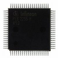
PEB2255H-V13 Infineon Technologies, PEB2255H-V13 Datasheet - Page 217

PEB2255H-V13
Manufacturer Part Number
PEB2255H-V13
Description
IC INTERFACE LINE 80-MQFP
Manufacturer
Infineon Technologies
Datasheet
1.PEB2255H-V13.pdf
(374 pages)
Specifications of PEB2255H-V13
Applications
*
Interface
*
Voltage - Supply
*
Package / Case
80-SQFP
Mounting Type
Surface Mount
Lead Free Status / RoHS Status
Lead free / RoHS Compliant
Other names
PEB2255H-V13
PEB2255H-V13IN
PEB2255H-V13IN
Available stocks
Company
Part Number
Manufacturer
Quantity
Price
Company:
Part Number:
PEB2255H-V13
Manufacturer:
Infineon Technologies
Quantity:
10 000
- Current page: 217 of 374
- Download datasheet (6Mb)
Line Interface Mode 2 (Read/Write)
Value after RESET: 00
DJA2…
DJA1…
SCF…
ELT…
Data Sheet
LIM2
7
Digital Jitter Attenuation DCO-X
0…
1…
Digital Jitter Attenuation DCO-R
0…
1…
Select Corner Frequency of DCO-R
Setting this bit reduces the corner frequency of the DCO-R circuit by
the factor of ten to 0.2 Hz.
Note: Reducing the corner frequency of the DCO-R circuitry
increases the synchronization time before the frequencies are
synchronized.
Enable Loop-Timed
0…
1…
4 which is synchronized with the extracted receive route clock. In this
configuration the transmit elastic buffer has to be enabled. Refer to
register XSW.XTM.
H
Jitter attenuation of the transmit clock is done using an external
pullable crystal between pins XTAL3/4
Jitter attenuation of the transmit clock is done without using an
external pullable crystal between pins XTAL3/4. Only a free
running 16.384-MHz clock has top be provided at XTAL3 (+/-
50 ppm).
Jitter attenuation of the system/transmit clock is done using an
external pullable crystal between pins XTAL1/2
Jitter attenuation of the system/transmit clock is done without
using an external pullable crystal between pins XTAL1/2. Only
a free running 16.384-MHz clock has top be provided at XTAL1
(+/- 50 ppm).
normal operation.
Transmit clock is generated from the clock supplied by XTAL3/
DJA2
DJA1
217
SCF
ELT
LOS2
FALC-LH V1.3
LOS1
E1 Registers
0
PEB 2255
2000-07
(38)
Related parts for PEB2255H-V13
Image
Part Number
Description
Manufacturer
Datasheet
Request
R

Part Number:
Description:
E1/t1/j1 Framer And Line Interface Component For Long And Short Haul Applications
Manufacturer:
Infineon Technologies Corporation
Datasheet:

Part Number:
Description:
Manufacturer:
Infineon Technologies AG
Datasheet:

Part Number:
Description:
Manufacturer:
Infineon Technologies AG
Datasheet:

Part Number:
Description:
Manufacturer:
Infineon Technologies AG
Datasheet:

Part Number:
Description:
Manufacturer:
Infineon Technologies AG
Datasheet:

Part Number:
Description:
Manufacturer:
Infineon Technologies AG
Datasheet:

Part Number:
Description:
Manufacturer:
Infineon Technologies AG
Datasheet:

Part Number:
Description:
Manufacturer:
Infineon Technologies AG
Datasheet:

Part Number:
Description:
16-bit microcontroller with 2x2 KByte RAM
Manufacturer:
Infineon Technologies AG
Datasheet:

Part Number:
Description:
NPN silicon RF transistor
Manufacturer:
Infineon Technologies AG
Datasheet:

Part Number:
Description:
NPN silicon RF transistor
Manufacturer:
Infineon Technologies AG
Datasheet:

Part Number:
Description:
NPN silicon RF transistor
Manufacturer:
Infineon Technologies AG
Datasheet:

Part Number:
Description:
NPN silicon RF transistor
Manufacturer:
Infineon Technologies AG
Datasheet:

Part Number:
Description:
Si-MMIC-amplifier in SIEGET 25-technologie
Manufacturer:
Infineon Technologies AG
Datasheet:

Part Number:
Description:
IGBT Power Module
Manufacturer:
Infineon Technologies AG
Datasheet:


