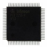
PEB2255H-V13 Infineon Technologies, PEB2255H-V13 Datasheet - Page 36

PEB2255H-V13
Manufacturer Part Number
PEB2255H-V13
Description
IC INTERFACE LINE 80-MQFP
Manufacturer
Infineon Technologies
Datasheet
1.PEB2255H-V13.pdf
(374 pages)
Specifications of PEB2255H-V13
Applications
*
Interface
*
Voltage - Supply
*
Package / Case
80-SQFP
Mounting Type
Surface Mount
Lead Free Status / RoHS Status
Lead free / RoHS Compliant
Other names
PEB2255H-V13
PEB2255H-V13IN
PEB2255H-V13IN
Available stocks
Company
Part Number
Manufacturer
Quantity
Price
Company:
Part Number:
PEB2255H-V13
Manufacturer:
Infineon Technologies
Quantity:
10 000
- Current page: 36 of 374
- Download datasheet (6Mb)
Table 4
Pin No.
71
Data Sheet
RFSP
Symbol
FREEZS
Pin Definitions - System Interface (cont’d)
Input (I)
Output (O)
Supply (S)
O
O
O
Function
Receive Frame Synchronous Pulse
E1: FMR3.CFRZ = 0
T1/J1: XC0.SFRZ = 0
Active low framing pulse derived from the
received PCM route signal. During loss of
synchronization (bit FRS0.LFA) this pulse is
suppressed (not influenced during alarm
simulation).
The pulse frequency is 8 kHz, pulse width is 488
ns (E1) or 648 ns (T1/J1).
PRBS Monitor Status
The status of the PRBS monitor is output on this
pin, if FMR3.CFRZ = 0 (E1) or XC0.SFRZ = 1
(T1/J1) and LCR1.EPRM = 1. It is set high, if the
PRBS monitor is in synchronous state.
Freeze Signaling (T1/J1)
If XC0.SFRZ = 1 (T1/J1) or FMR3.CFRZ = 1
(E1) and LCR1.EPRM = 0, the Freeze Signaling
Status is indicated.
Register access
(LOOP.SPN=0 and LIM3.ESY=0):
• E1: Bit FRS1.TSL16LFA = 1
• T1: FRS0.LFA/LMFA = 1
Serial signaling access
(LOOP.SPN=1 and LIM3.ESY=1):
• E1: Bit FRS1.TSL16LFA = 1
• T1: FRS0.LFA/LMFA = 1
The signal is cleared after an error-free
superframe. During alarm simulation this signal
gets active during simulation steps 2 and 6.
or a receive slip (positive or negative)
occurred
or FRS0.LOS=1
or a receive slip occurred
or FRS0.LOS=1
or a receive slip occurred
36
Pin Descriptions
FALC-LH V1.3
PEB 2255
2000-07
Related parts for PEB2255H-V13
Image
Part Number
Description
Manufacturer
Datasheet
Request
R

Part Number:
Description:
E1/t1/j1 Framer And Line Interface Component For Long And Short Haul Applications
Manufacturer:
Infineon Technologies Corporation
Datasheet:

Part Number:
Description:
Manufacturer:
Infineon Technologies AG
Datasheet:

Part Number:
Description:
Manufacturer:
Infineon Technologies AG
Datasheet:

Part Number:
Description:
Manufacturer:
Infineon Technologies AG
Datasheet:

Part Number:
Description:
Manufacturer:
Infineon Technologies AG
Datasheet:

Part Number:
Description:
Manufacturer:
Infineon Technologies AG
Datasheet:

Part Number:
Description:
Manufacturer:
Infineon Technologies AG
Datasheet:

Part Number:
Description:
Manufacturer:
Infineon Technologies AG
Datasheet:

Part Number:
Description:
16-bit microcontroller with 2x2 KByte RAM
Manufacturer:
Infineon Technologies AG
Datasheet:

Part Number:
Description:
NPN silicon RF transistor
Manufacturer:
Infineon Technologies AG
Datasheet:

Part Number:
Description:
NPN silicon RF transistor
Manufacturer:
Infineon Technologies AG
Datasheet:

Part Number:
Description:
NPN silicon RF transistor
Manufacturer:
Infineon Technologies AG
Datasheet:

Part Number:
Description:
NPN silicon RF transistor
Manufacturer:
Infineon Technologies AG
Datasheet:

Part Number:
Description:
Si-MMIC-amplifier in SIEGET 25-technologie
Manufacturer:
Infineon Technologies AG
Datasheet:

Part Number:
Description:
IGBT Power Module
Manufacturer:
Infineon Technologies AG
Datasheet:


