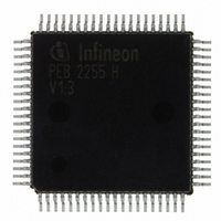
PEB2255H-V13 Infineon Technologies, PEB2255H-V13 Datasheet - Page 26

PEB2255H-V13
Manufacturer Part Number
PEB2255H-V13
Description
IC INTERFACE LINE 80-MQFP
Manufacturer
Infineon Technologies
Datasheet
1.PEB2255H-V13.pdf
(374 pages)
Specifications of PEB2255H-V13
Applications
*
Interface
*
Voltage - Supply
*
Package / Case
80-SQFP
Mounting Type
Surface Mount
Lead Free Status / RoHS Status
Lead free / RoHS Compliant
Other names
PEB2255H-V13
PEB2255H-V13IN
PEB2255H-V13IN
Available stocks
Company
Part Number
Manufacturer
Quantity
Price
Company:
Part Number:
PEB2255H-V13
Manufacturer:
Infineon Technologies
Quantity:
10 000
- Current page: 26 of 374
- Download datasheet (6Mb)
Table 1
Pin No.
50
51
11
8
Data Sheet
Pin Definitions - Microprocessor Interface (cont’d)
Symbol
RD/DS
WR/RW
DBW
IM
Input (I)
Output (O)
Supply (S)
I
I
I
I
Function
Read Enable (Intel bus mode)
This signal indicates a read operation. When
the FALC
signal enables the bus drivers to output data
from an internal register addressed by
A0 … A6 on to the Data Bus.
Data Strobe (Motorola bus mode)
This pin serves as input to control read/write
operations. It is logically ored with pin CS.
Write Enable (Intel bus mode)
This signal indicates a write operation. When
CS is active the FALC
register with data provided on the Data Bus.
Read/Write Enable (Motorola bus mode)
This signal distinguishes between read and
write operation.
Data Bus Width (Bus Interface Mode)
A low signal on this input selects the 8-bit bus
interface mode. A high signal on this input
selects the 16-bit bus interface mode. In this
case word transfer to/from the internal
registers is enabled. Byte transfers are
implemented by using A0 and BHE/BLE.
Interface Mode
The level at this pin defines the bus interface
mode:
A low signal on this input selects the Intel
interface mode. A high signal on this input
selects the Motorola interface mode.
26
®
-LH is selected via CS, the RD
®
-LH loads an internal
Pin Descriptions
FALC-LH V1.3
PEB 2255
2000-07
Related parts for PEB2255H-V13
Image
Part Number
Description
Manufacturer
Datasheet
Request
R

Part Number:
Description:
E1/t1/j1 Framer And Line Interface Component For Long And Short Haul Applications
Manufacturer:
Infineon Technologies Corporation
Datasheet:

Part Number:
Description:
Manufacturer:
Infineon Technologies AG
Datasheet:

Part Number:
Description:
Manufacturer:
Infineon Technologies AG
Datasheet:

Part Number:
Description:
Manufacturer:
Infineon Technologies AG
Datasheet:

Part Number:
Description:
Manufacturer:
Infineon Technologies AG
Datasheet:

Part Number:
Description:
Manufacturer:
Infineon Technologies AG
Datasheet:

Part Number:
Description:
Manufacturer:
Infineon Technologies AG
Datasheet:

Part Number:
Description:
Manufacturer:
Infineon Technologies AG
Datasheet:

Part Number:
Description:
16-bit microcontroller with 2x2 KByte RAM
Manufacturer:
Infineon Technologies AG
Datasheet:

Part Number:
Description:
NPN silicon RF transistor
Manufacturer:
Infineon Technologies AG
Datasheet:

Part Number:
Description:
NPN silicon RF transistor
Manufacturer:
Infineon Technologies AG
Datasheet:

Part Number:
Description:
NPN silicon RF transistor
Manufacturer:
Infineon Technologies AG
Datasheet:

Part Number:
Description:
NPN silicon RF transistor
Manufacturer:
Infineon Technologies AG
Datasheet:

Part Number:
Description:
Si-MMIC-amplifier in SIEGET 25-technologie
Manufacturer:
Infineon Technologies AG
Datasheet:

Part Number:
Description:
IGBT Power Module
Manufacturer:
Infineon Technologies AG
Datasheet:


