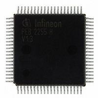
PEB2255H-V13 Infineon Technologies, PEB2255H-V13 Datasheet - Page 157

PEB2255H-V13
Manufacturer Part Number
PEB2255H-V13
Description
IC INTERFACE LINE 80-MQFP
Manufacturer
Infineon Technologies
Datasheet
1.PEB2255H-V13.pdf
(374 pages)
Specifications of PEB2255H-V13
Applications
*
Interface
*
Voltage - Supply
*
Package / Case
80-SQFP
Mounting Type
Surface Mount
Lead Free Status / RoHS Status
Lead free / RoHS Compliant
Other names
PEB2255H-V13
PEB2255H-V13IN
PEB2255H-V13IN
Available stocks
Company
Part Number
Manufacturer
Quantity
Price
Company:
Part Number:
PEB2255H-V13
Manufacturer:
Infineon Technologies
Quantity:
10 000
- Current page: 157 of 374
- Download datasheet (6Mb)
PEB 2255
FALC-LH V1.3
Functional Description T1/J1
5.6.6
Alarm Simulation (T1/J1)
Alarm simulation does not affect the normal operation of the device, i.e. all time slots
remain available for transmission. However, possible “real“ alarm conditions are not
reported to the processor or to the remote end when the device is in the alarm simulation
mode.
The alarm simulation is initiated by setting the bit FMR0.SIM. The following alarms are
simulated:
• Loss of Signal (red alarm)
• Alarm Indication Signal AIS (blue alarm)
• Loss of pulse frame
• Remote alarm (yellow alarm) indication
• Receive and transmit slip indication
• Framing error counter
• Code violation counter
• CRC6 error counter
®
Some of the above indications are only simulated if the FALC
-LH is configured in a
mode where the alarm is applicable.
The alarm simulation is controlled by the value of the Alarm Simulation Counter:
FRS2.ESC which is incremented by setting bit: FMR0.SIM.
Clearing of alarm indications:
• Automatically for LOS, remote (yellow) alarm, AIS, and loss of synchronization or
• User controlled for slips by reading the corresponding interrupt status register ISR3 or
• Error counter have been cleared by reading the corresponding counter registers.
Clearing is only possible at defined counter steps of FRS2.ESC. For complete simulation
(FRS2.ESC = 0), eight simulation steps are necessary.
Data Sheet
157
2000-07
Related parts for PEB2255H-V13
Image
Part Number
Description
Manufacturer
Datasheet
Request
R

Part Number:
Description:
E1/t1/j1 Framer And Line Interface Component For Long And Short Haul Applications
Manufacturer:
Infineon Technologies Corporation
Datasheet:

Part Number:
Description:
Manufacturer:
Infineon Technologies AG
Datasheet:

Part Number:
Description:
Manufacturer:
Infineon Technologies AG
Datasheet:

Part Number:
Description:
Manufacturer:
Infineon Technologies AG
Datasheet:

Part Number:
Description:
Manufacturer:
Infineon Technologies AG
Datasheet:

Part Number:
Description:
Manufacturer:
Infineon Technologies AG
Datasheet:

Part Number:
Description:
Manufacturer:
Infineon Technologies AG
Datasheet:

Part Number:
Description:
Manufacturer:
Infineon Technologies AG
Datasheet:

Part Number:
Description:
16-bit microcontroller with 2x2 KByte RAM
Manufacturer:
Infineon Technologies AG
Datasheet:

Part Number:
Description:
NPN silicon RF transistor
Manufacturer:
Infineon Technologies AG
Datasheet:

Part Number:
Description:
NPN silicon RF transistor
Manufacturer:
Infineon Technologies AG
Datasheet:

Part Number:
Description:
NPN silicon RF transistor
Manufacturer:
Infineon Technologies AG
Datasheet:

Part Number:
Description:
NPN silicon RF transistor
Manufacturer:
Infineon Technologies AG
Datasheet:

Part Number:
Description:
Si-MMIC-amplifier in SIEGET 25-technologie
Manufacturer:
Infineon Technologies AG
Datasheet:

Part Number:
Description:
IGBT Power Module
Manufacturer:
Infineon Technologies AG
Datasheet:


