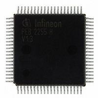
PEB2255H-V13 Infineon Technologies, PEB2255H-V13 Datasheet - Page 310

PEB2255H-V13
Manufacturer Part Number
PEB2255H-V13
Description
IC INTERFACE LINE 80-MQFP
Manufacturer
Infineon Technologies
Datasheet
1.PEB2255H-V13.pdf
(374 pages)
Specifications of PEB2255H-V13
Applications
*
Interface
*
Voltage - Supply
*
Package / Case
80-SQFP
Mounting Type
Surface Mount
Lead Free Status / RoHS Status
Lead free / RoHS Compliant
Other names
PEB2255H-V13
PEB2255H-V13IN
PEB2255H-V13IN
Available stocks
Company
Part Number
Manufacturer
Quantity
Price
Company:
Part Number:
PEB2255H-V13
Manufacturer:
Infineon Technologies
Quantity:
10 000
- Current page: 310 of 374
- Download datasheet (6Mb)
RES4…0...
Framer Receive Status Register 0 (Read)
LOS…
Data Sheet
FRS0
LOS
7
Receive Equalizer Status
The current line attenuation status in steps of about 1.4 dB are
displayed in these bits. Only valid if bits EV1/0 = 01 and
LIM1.EQON=1.
Accuracy: +/- 2 digit, based on temperature influence and noise
amplitude variations.
00000… attenuation: 0 dB
...
11001… max. attenuation: -36 dB
Loss of Signal (Red Alarm)
Detection:
This bit is set when the incoming signal has „no transitions“ (analog
interface) or logical zeros (dig. interface) in a time interval of T
consecutive pulses, where T is programmable via PCD register:
Total account of consecutive pulses: 16 < T < 4096.
Analog interface: The receive signal level where “no transition” is
declared is defined by the programmed value of LIM1.RIL2...0.
Recovery:
Analog interface: The bit is reset in short haul mode when the
incoming signal has transitions with signal levels greater than the
programmed receive input level (LIM1.RIL2...0) for at least M pulse
periods defined by register PCR in the PCD time interval. In long haul
mode additionally bit RES.6 must be set for at least 250µsec.
Digital interface: The bit is reset when the incoming data stream
contains at least M ones defined by register PCR in the PCD time
interval.
With the rising edge of this bit an interrupt status bit (ISR2.LOS) is set.
For additionally recovery conditions refer also to register LIM2.LOS1.
The bit is set during alarm simulation and reset if FRS2.ESC = 0, 3,
4, 6,7 and no alarm condition exists.
AIS
LFA
RRA
310
LMFA
FALC-LH V1.3
T1/J1 Registers
FSRF
0
PEB 2255
2000-07
(4C)
Related parts for PEB2255H-V13
Image
Part Number
Description
Manufacturer
Datasheet
Request
R

Part Number:
Description:
E1/t1/j1 Framer And Line Interface Component For Long And Short Haul Applications
Manufacturer:
Infineon Technologies Corporation
Datasheet:

Part Number:
Description:
Manufacturer:
Infineon Technologies AG
Datasheet:

Part Number:
Description:
Manufacturer:
Infineon Technologies AG
Datasheet:

Part Number:
Description:
Manufacturer:
Infineon Technologies AG
Datasheet:

Part Number:
Description:
Manufacturer:
Infineon Technologies AG
Datasheet:

Part Number:
Description:
Manufacturer:
Infineon Technologies AG
Datasheet:

Part Number:
Description:
Manufacturer:
Infineon Technologies AG
Datasheet:

Part Number:
Description:
Manufacturer:
Infineon Technologies AG
Datasheet:

Part Number:
Description:
16-bit microcontroller with 2x2 KByte RAM
Manufacturer:
Infineon Technologies AG
Datasheet:

Part Number:
Description:
NPN silicon RF transistor
Manufacturer:
Infineon Technologies AG
Datasheet:

Part Number:
Description:
NPN silicon RF transistor
Manufacturer:
Infineon Technologies AG
Datasheet:

Part Number:
Description:
NPN silicon RF transistor
Manufacturer:
Infineon Technologies AG
Datasheet:

Part Number:
Description:
NPN silicon RF transistor
Manufacturer:
Infineon Technologies AG
Datasheet:

Part Number:
Description:
Si-MMIC-amplifier in SIEGET 25-technologie
Manufacturer:
Infineon Technologies AG
Datasheet:

Part Number:
Description:
IGBT Power Module
Manufacturer:
Infineon Technologies AG
Datasheet:


