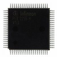
PEB2255H-V13 Infineon Technologies, PEB2255H-V13 Datasheet - Page 88

PEB2255H-V13
Manufacturer Part Number
PEB2255H-V13
Description
IC INTERFACE LINE 80-MQFP
Manufacturer
Infineon Technologies
Datasheet
1.PEB2255H-V13.pdf
(374 pages)
Specifications of PEB2255H-V13
Applications
*
Interface
*
Voltage - Supply
*
Package / Case
80-SQFP
Mounting Type
Surface Mount
Lead Free Status / RoHS Status
Lead free / RoHS Compliant
Other names
PEB2255H-V13
PEB2255H-V13IN
PEB2255H-V13IN
Available stocks
Company
Part Number
Manufacturer
Quantity
Price
Company:
Part Number:
PEB2255H-V13
Manufacturer:
Infineon Technologies
Quantity:
10 000
- Current page: 88 of 374
- Download datasheet (6Mb)
In doubleframe asynchronous state, counting of framing errors, CRC4 bit errors and
detection of remote alarm is stopped. AIS is automatically sent to the backplane interface
(can be disabled via bit FMR2.DAIS). Further on the updating of the registers RSA6S
and RS1-16 is halted (remote alarm indication, S
The multiframe synchronous state is established after detecting two correct multiframe
alignment signals at an interval of n
alignment flag FRS0.LMFA is reset. Additionally an interrupt status multiframe alignment
recovery bit ISR2.MFAR is generated with the falling edge of bit FRS0.LMFA.
4.4.3.2
In addition, a search for Doubleframe alignment is automatically initiated if two
multiframe pattern with a distance of n
of 8 ms after doubleframe alignment has been regained (bit FMR1.AFR). A new search
for frame alignment is started just after the previous frame alignment signal.
4.4.3.3
After reaching doubleframe synchronization a 8 ms timer is started. If a multiframe
alignment signal is found during the 8 ms time interval the internal timer is reset to
remaining 6 ms in order to find the next multiframe signal within this time. If the
multiframe signal is not found for a second time an interrupt status ISR0.T8MS is
provided. This interrupt usually occurs every 8 ms until multiframe synchronization is
achieved.
4.4.3.4
In the synchronous state checking of multiframe pattern is disabled. However, with bit
FMR2.ALMF an automatic multiframe resynchronization mode can be activated. If 915
out of 1000 errored CRC submultiframes are found then a false frame alignment is
assumed and a search for double- and multiframe pattern is initiated. The new search
for frame alignment is started just after the previous basic frame alignment signal.
4.4.3.5
The modified CRC4 multiframe alignment algorithm allows an automatic interworking
between framers with and without a CRC4 capability. The interworking is realized as it
is described in ITU-T G.706 Appendix B and shown in
If doubleframe synchronization is consistently present but CRC4 multiframe alignment is
not achieved within 400 ms it is assumed that the distant end is initialized to doubleframe
format. The CRC4 to non-CRC4 interworking is enabled via FMR2.RFS1/0 = 11 and is
activated only if the receiver has lost its synchronization. If doubleframe alignment (basic
frame alignment) is established a 400 ms timer and searching for multiframe alignment
is started. A research for basic frame alignment is initiated if the CRC4 multiframe
Data Sheet
Automatic Force Resynchronization (E1)
Floating Multiframe Alignment Window (E1)
CRC4 Performance Monitoring (E1)
Modified CRC4 Multiframe Alignment Algorithm (E1)
2 ms (n = 1, 2, 3 …). The Loss of multiframe
2 ms have not been found within a time interval
88
a
/S
i
-bit access).
Figure 4.5
Functional Description E1
on
page
FALC-LH V1.3
93.
PEB 2255
2000-07
Related parts for PEB2255H-V13
Image
Part Number
Description
Manufacturer
Datasheet
Request
R

Part Number:
Description:
E1/t1/j1 Framer And Line Interface Component For Long And Short Haul Applications
Manufacturer:
Infineon Technologies Corporation
Datasheet:

Part Number:
Description:
Manufacturer:
Infineon Technologies AG
Datasheet:

Part Number:
Description:
Manufacturer:
Infineon Technologies AG
Datasheet:

Part Number:
Description:
Manufacturer:
Infineon Technologies AG
Datasheet:

Part Number:
Description:
Manufacturer:
Infineon Technologies AG
Datasheet:

Part Number:
Description:
Manufacturer:
Infineon Technologies AG
Datasheet:

Part Number:
Description:
Manufacturer:
Infineon Technologies AG
Datasheet:

Part Number:
Description:
Manufacturer:
Infineon Technologies AG
Datasheet:

Part Number:
Description:
16-bit microcontroller with 2x2 KByte RAM
Manufacturer:
Infineon Technologies AG
Datasheet:

Part Number:
Description:
NPN silicon RF transistor
Manufacturer:
Infineon Technologies AG
Datasheet:

Part Number:
Description:
NPN silicon RF transistor
Manufacturer:
Infineon Technologies AG
Datasheet:

Part Number:
Description:
NPN silicon RF transistor
Manufacturer:
Infineon Technologies AG
Datasheet:

Part Number:
Description:
NPN silicon RF transistor
Manufacturer:
Infineon Technologies AG
Datasheet:

Part Number:
Description:
Si-MMIC-amplifier in SIEGET 25-technologie
Manufacturer:
Infineon Technologies AG
Datasheet:

Part Number:
Description:
IGBT Power Module
Manufacturer:
Infineon Technologies AG
Datasheet:


