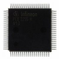
PEB2255H-V13 Infineon Technologies, PEB2255H-V13 Datasheet - Page 294

PEB2255H-V13
Manufacturer Part Number
PEB2255H-V13
Description
IC INTERFACE LINE 80-MQFP
Manufacturer
Infineon Technologies
Datasheet
1.PEB2255H-V13.pdf
(374 pages)
Specifications of PEB2255H-V13
Applications
*
Interface
*
Voltage - Supply
*
Package / Case
80-SQFP
Mounting Type
Surface Mount
Lead Free Status / RoHS Status
Lead free / RoHS Compliant
Other names
PEB2255H-V13
PEB2255H-V13IN
PEB2255H-V13IN
Available stocks
Company
Part Number
Manufacturer
Quantity
Price
Company:
Part Number:
PEB2255H-V13
Manufacturer:
Infineon Technologies
Quantity:
10 000
- Current page: 294 of 374
- Download datasheet (6Mb)
JATT…RL...
DRS…
Pulse Count Detection Register (Read/Write)
Value after RESET: 00
PCD7…PCD0… Pulse Count Detection
Data Sheet
PCD
PCD7
7
Transmit Jitter Attenuator/Remote Loop
00 = Normal operation. The transmit jitter attenuator is disabled.
01 = Remote Loop active without transmit jitter attenuator enabled.
10 = not assigned
11 = Remote Loop and jitter attenuator active. Received data from
A LOS alarm (red alarm) is detected if the incoming data stream has
no transitions for a programmable number T consecutive pulse
positions. The number T is programmable via the PCD register and
can be calculated as follows:
T= 16(N+1) ; with 0
The maximum time is: 256
pulse resets the internal pulse counter. The counter is clocked with
the receive clock RCLK.
0 =
1 =
Dual Rail Select
H
Transmit data bypasses the buffer.
Transmit data bypasses the buffer.
pins RL1/2 or RDIP/N or ROID is sent ’jitter free’ on ports XL1/
2 or XDOP/N or XOID. The dejittered clock is generated by the
DCO-X circuitry.
The ternary interface is selected. Multifunction ports RL1/2 and
XL1/2 become analog in/outputs.
The digital dual rail interface is selected. Received data is
latched on multifunction ports RDIP/RDIN while transmit data is
output on pins XDOP/XDON.
N
294
255.
16
648 ns = 2.65 ms. Every detected
FALC-LH V1.3
T1/J1 Registers
PCD0
0
PEB 2255
2000-07
(36)
Related parts for PEB2255H-V13
Image
Part Number
Description
Manufacturer
Datasheet
Request
R

Part Number:
Description:
E1/t1/j1 Framer And Line Interface Component For Long And Short Haul Applications
Manufacturer:
Infineon Technologies Corporation
Datasheet:

Part Number:
Description:
Manufacturer:
Infineon Technologies AG
Datasheet:

Part Number:
Description:
Manufacturer:
Infineon Technologies AG
Datasheet:

Part Number:
Description:
Manufacturer:
Infineon Technologies AG
Datasheet:

Part Number:
Description:
Manufacturer:
Infineon Technologies AG
Datasheet:

Part Number:
Description:
Manufacturer:
Infineon Technologies AG
Datasheet:

Part Number:
Description:
Manufacturer:
Infineon Technologies AG
Datasheet:

Part Number:
Description:
Manufacturer:
Infineon Technologies AG
Datasheet:

Part Number:
Description:
16-bit microcontroller with 2x2 KByte RAM
Manufacturer:
Infineon Technologies AG
Datasheet:

Part Number:
Description:
NPN silicon RF transistor
Manufacturer:
Infineon Technologies AG
Datasheet:

Part Number:
Description:
NPN silicon RF transistor
Manufacturer:
Infineon Technologies AG
Datasheet:

Part Number:
Description:
NPN silicon RF transistor
Manufacturer:
Infineon Technologies AG
Datasheet:

Part Number:
Description:
NPN silicon RF transistor
Manufacturer:
Infineon Technologies AG
Datasheet:

Part Number:
Description:
Si-MMIC-amplifier in SIEGET 25-technologie
Manufacturer:
Infineon Technologies AG
Datasheet:

Part Number:
Description:
IGBT Power Module
Manufacturer:
Infineon Technologies AG
Datasheet:


