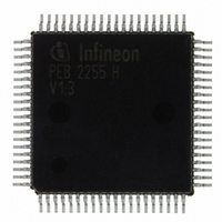
PEB2255H-V13 Infineon Technologies, PEB2255H-V13 Datasheet - Page 80

PEB2255H-V13
Manufacturer Part Number
PEB2255H-V13
Description
IC INTERFACE LINE 80-MQFP
Manufacturer
Infineon Technologies
Datasheet
1.PEB2255H-V13.pdf
(374 pages)
Specifications of PEB2255H-V13
Applications
*
Interface
*
Voltage - Supply
*
Package / Case
80-SQFP
Mounting Type
Surface Mount
Lead Free Status / RoHS Status
Lead free / RoHS Compliant
Other names
PEB2255H-V13
PEB2255H-V13IN
PEB2255H-V13IN
Available stocks
Company
Part Number
Manufacturer
Quantity
Price
Company:
Part Number:
PEB2255H-V13
Manufacturer:
Infineon Technologies
Quantity:
10 000
- Current page: 80 of 374
- Download datasheet (6Mb)
Similar to the receive line interface three different data types are supported:
• Ternary Signal
• Dual rail data PCM(+), PCM(–) at multifunction ports XDOP/XDON with 50 % or
• Unipolar data on port XOID is transmitted either in NRZ (Non Return to Zero) with
4.3.5
The analog transmitter includes a programmable pulse shaper to satisfy the
requirements of ITU-T I.431. The amplitude and shape of the transmit pulses are
completely programmable via registers XPM0...2 from the microprocessor interface.
The transmitter requires an external step up transformer to drive the line.
4.3.6
The transmit line monitor compares the transmit line pulses on XL1 and XL2 with the
transmit input signals received on pins XL1M and XL2M. The monitor detects faults on
the primary side of the transformer and protects the device from damage by setting the
transmit lines into high impedance state automatically. Faults on the secondary side can
not be detected. To detect shorts, the configuration shown in
provided and the default (reset) value of registers XPM0...2 must be selected. Otherwise
a short detection can not be guaranteed. Two conditions are detected by the monitor:
“Transmit Line Ones Density“ (more than 31 consecutive zeroes) and “Transmit Line
Shorted“. In both cases a transmit line monitor status change interrupt is provided.
Data Sheet
Single rail data is converted into a ternary signal which is output on pins XL1 and XL2.
The HDB3 and AMI line code is employed. Selected by FMR0.XC1/0 and
LIM1.DRS = 0.
100 % duty cycle and with programmable polarity. Line coding is done in the same
way as in the ternary interface. Selected by FMR0.XC1/0 and LIM1.DRS = 1.
100 % duty cycle or in CMI (Code Mark Inversion or known as 1T2B) Code with or
without (FMR3.CMI) preprocessed HDB3 coding to a fibre optical interface. Clocking
off data is done with the rising edge of the transmit clock XCLK (2048 kHz) and with
a programmable polarity. Selection is done by FMR0.XC1 = 0 and LIM1.DRS = 1.
Programmable Pulse Shaper (E1)
Transmit Line Monitor (E1)
80
Functional Description E1
Figure 24
FALC-LH V1.3
PEB 2255
must be
2000-07
Related parts for PEB2255H-V13
Image
Part Number
Description
Manufacturer
Datasheet
Request
R

Part Number:
Description:
E1/t1/j1 Framer And Line Interface Component For Long And Short Haul Applications
Manufacturer:
Infineon Technologies Corporation
Datasheet:

Part Number:
Description:
Manufacturer:
Infineon Technologies AG
Datasheet:

Part Number:
Description:
Manufacturer:
Infineon Technologies AG
Datasheet:

Part Number:
Description:
Manufacturer:
Infineon Technologies AG
Datasheet:

Part Number:
Description:
Manufacturer:
Infineon Technologies AG
Datasheet:

Part Number:
Description:
Manufacturer:
Infineon Technologies AG
Datasheet:

Part Number:
Description:
Manufacturer:
Infineon Technologies AG
Datasheet:

Part Number:
Description:
Manufacturer:
Infineon Technologies AG
Datasheet:

Part Number:
Description:
16-bit microcontroller with 2x2 KByte RAM
Manufacturer:
Infineon Technologies AG
Datasheet:

Part Number:
Description:
NPN silicon RF transistor
Manufacturer:
Infineon Technologies AG
Datasheet:

Part Number:
Description:
NPN silicon RF transistor
Manufacturer:
Infineon Technologies AG
Datasheet:

Part Number:
Description:
NPN silicon RF transistor
Manufacturer:
Infineon Technologies AG
Datasheet:

Part Number:
Description:
NPN silicon RF transistor
Manufacturer:
Infineon Technologies AG
Datasheet:

Part Number:
Description:
Si-MMIC-amplifier in SIEGET 25-technologie
Manufacturer:
Infineon Technologies AG
Datasheet:

Part Number:
Description:
IGBT Power Module
Manufacturer:
Infineon Technologies AG
Datasheet:


