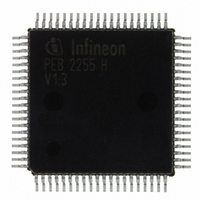
PEB2255H-V13 Infineon Technologies, PEB2255H-V13 Datasheet - Page 214

PEB2255H-V13
Manufacturer Part Number
PEB2255H-V13
Description
IC INTERFACE LINE 80-MQFP
Manufacturer
Infineon Technologies
Datasheet
1.PEB2255H-V13.pdf
(374 pages)
Specifications of PEB2255H-V13
Applications
*
Interface
*
Voltage - Supply
*
Package / Case
80-SQFP
Mounting Type
Surface Mount
Lead Free Status / RoHS Status
Lead free / RoHS Compliant
Other names
PEB2255H-V13
PEB2255H-V13IN
PEB2255H-V13IN
Available stocks
Company
Part Number
Manufacturer
Quantity
Price
Company:
Part Number:
PEB2255H-V13
Manufacturer:
Infineon Technologies
Quantity:
10 000
- Current page: 214 of 374
- Download datasheet (6Mb)
LL…
MAS…
Line Interface Mode 1 (Read/Write)
Value after RESET: 00
EFSC…
RIL2…0…
Note: LIM1.RIL(2:0) must be programmed before LIM0.EQON = 1 is set.
Data Sheet
LIM1
EFSC
7
Local Loop
0…
1…
Master Mode
0…
Enable Frame Synchronization Pulse
0…
1…
Receive Input Threshold
Only valid if analog line interface in short haul mode is selected
(LIM0.EQON=0 and LIM1.DRS=0).
Loss of signal is declared if the voltage between pins RL1 and RL2
drops below the limits programmed via bits RIL2...0 and the received
data stream has no transition for a period defined in the PCD register.
The threshold where no signal is declared is programmable by the
RIL2...0 bits, see
1
RIL2
H
Normal operation
Local loop active. The local loopback mode disconnects the
receive lines RL1/RL2 or RDIP/RDIN from the receiver. Instead
of the signals coming from the line the data provided by system
interface are routed through the analog receiver back to the
system interface. The unipolar bit stream is transmitted
undisturbedly on the line. Receiver and transmitter coding must
be identical. Operates in analog and digital line interface mode.
In analog line interface mode data is transferred through the
complete analog receiver.
Slave mode
Master mode on. Setting this bit the DCO-R circuitry is
frequency synchronized with the clock (2.048 MHz) supplied by
SYNC. If this pin is connected to VSS the DCO-R circuitry is
centered and no receive jitter attenuation is performed. The
generated clocks are stable.
The transmit clock is output via pin XCLK.
Pin XCLK provides a 8 kHz frame synchronization pulse which
is active high for one 2 MHz cycle (pulse width = 488 ns).
RIL1
Table 58 "DC Parameters" on page 336
RIL0
214
TCD1
JATT
RL
FALC-LH V1.3
DRS
E1 Registers
0
PEB 2255
for detail.
2000-07
(35)
Related parts for PEB2255H-V13
Image
Part Number
Description
Manufacturer
Datasheet
Request
R

Part Number:
Description:
E1/t1/j1 Framer And Line Interface Component For Long And Short Haul Applications
Manufacturer:
Infineon Technologies Corporation
Datasheet:

Part Number:
Description:
Manufacturer:
Infineon Technologies AG
Datasheet:

Part Number:
Description:
Manufacturer:
Infineon Technologies AG
Datasheet:

Part Number:
Description:
Manufacturer:
Infineon Technologies AG
Datasheet:

Part Number:
Description:
Manufacturer:
Infineon Technologies AG
Datasheet:

Part Number:
Description:
Manufacturer:
Infineon Technologies AG
Datasheet:

Part Number:
Description:
Manufacturer:
Infineon Technologies AG
Datasheet:

Part Number:
Description:
Manufacturer:
Infineon Technologies AG
Datasheet:

Part Number:
Description:
16-bit microcontroller with 2x2 KByte RAM
Manufacturer:
Infineon Technologies AG
Datasheet:

Part Number:
Description:
NPN silicon RF transistor
Manufacturer:
Infineon Technologies AG
Datasheet:

Part Number:
Description:
NPN silicon RF transistor
Manufacturer:
Infineon Technologies AG
Datasheet:

Part Number:
Description:
NPN silicon RF transistor
Manufacturer:
Infineon Technologies AG
Datasheet:

Part Number:
Description:
NPN silicon RF transistor
Manufacturer:
Infineon Technologies AG
Datasheet:

Part Number:
Description:
Si-MMIC-amplifier in SIEGET 25-technologie
Manufacturer:
Infineon Technologies AG
Datasheet:

Part Number:
Description:
IGBT Power Module
Manufacturer:
Infineon Technologies AG
Datasheet:


