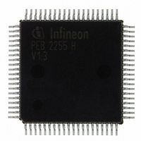
PEB2255H-V13 Infineon Technologies, PEB2255H-V13 Datasheet - Page 55

PEB2255H-V13
Manufacturer Part Number
PEB2255H-V13
Description
IC INTERFACE LINE 80-MQFP
Manufacturer
Infineon Technologies
Datasheet
1.PEB2255H-V13.pdf
(374 pages)
Specifications of PEB2255H-V13
Applications
*
Interface
*
Voltage - Supply
*
Package / Case
80-SQFP
Mounting Type
Surface Mount
Lead Free Status / RoHS Status
Lead free / RoHS Compliant
Other names
PEB2255H-V13
PEB2255H-V13IN
PEB2255H-V13IN
Available stocks
Company
Part Number
Manufacturer
Quantity
Price
Company:
Part Number:
PEB2255H-V13
Manufacturer:
Infineon Technologies
Quantity:
10 000
- Current page: 55 of 374
- Download datasheet (6Mb)
Long Haul Interface
The FALC
receive equalization network and noise filtering.
4.1.1
The FALC
up to -43 dB. The maximum reachable length with a 22 AWG twisted-pair cable is 1500
m. After reset the FALC
to -10 dB of cable attenuation. Switching in “Long Haul“ mode is done by setting of
register LIM0.EQON.
The integrated receive equalization network recovers signals with up to -43 dB of cable
attenuation. Noise filters eliminate the higher frequency part of the received signals. The
incoming data is peak detected and sliced at 55% of the peak value to produce the digital
data stream. The received data is then forwarded to the clock & data recovery unit.
The current equalizer status is indicated by register RES (Receive Equalizer Status) in
long haul mode.
4.1.2
Status register RES reports the current receive line attenuation in a range of 0 to -43 dB
in 25 steps of approximately 1.7 dB each. The least significant 5 bits of this register
indicate the cable attenuation in dB. These 5 bits are only valid in conjunction with the
two most significant bits (RES.EV1/0 = 01).
4.1.3
The analog received signal on port RL1/2 is equalized and then peak-detected to
produce a digital signal. The digital received signal on port RDIP/N is directly forwarded
to the DPLL. The receive clock and data recovery extracts the route clock RCLK from
the data stream received at the RL1/2, RDIP/RDIN or ROID lines and converts the data
stream into a single rail, unipolar bit stream. The clock and data recovery works with the
clock frequency supplied by XTAL1. Normally the clock that is output via pin RCLK is the
recovered clock from the signal provided on RL1/2 or RDIP/N and has a duty cycle close
to 50 %. The free run frequency is defined by XTAL1 divided by 8 in periods with no
signal. The intrinsic jitter generated in the absence of any input jitter is not more than
0.035 UI. In digital bipolar line interface mode the clock and data recovery accepts only
HDB3 or AMI coded signals with 50% duty cycle.
4.1.4
The HDB3 line code or the AMI coding is provided for the data received from the ternary
or the dual rail interface. In case of the optical interface a selection between the NRZ
code and the CMI Code (1T2B) with HDB3 postprocessing is provided. If CMI code
Data Sheet
®
®
-LH has an integrated short-haul and long-haul line interface, consisting of a
Receive Equalization Network (E1)
Receive Line Attenuation Indication (E1)
Receive Clock and Data Recovery (E1)
Receive Line Coding (E1)
-LH automatically recovers the signals received on pins RL1/2 in a range of
®
-LH is in “Short Haul“ mode, received signals are recovered up
55
Functional Description E1
FALC-LH V1.3
PEB 2255
2000-07
Related parts for PEB2255H-V13
Image
Part Number
Description
Manufacturer
Datasheet
Request
R

Part Number:
Description:
E1/t1/j1 Framer And Line Interface Component For Long And Short Haul Applications
Manufacturer:
Infineon Technologies Corporation
Datasheet:

Part Number:
Description:
Manufacturer:
Infineon Technologies AG
Datasheet:

Part Number:
Description:
Manufacturer:
Infineon Technologies AG
Datasheet:

Part Number:
Description:
Manufacturer:
Infineon Technologies AG
Datasheet:

Part Number:
Description:
Manufacturer:
Infineon Technologies AG
Datasheet:

Part Number:
Description:
Manufacturer:
Infineon Technologies AG
Datasheet:

Part Number:
Description:
Manufacturer:
Infineon Technologies AG
Datasheet:

Part Number:
Description:
Manufacturer:
Infineon Technologies AG
Datasheet:

Part Number:
Description:
16-bit microcontroller with 2x2 KByte RAM
Manufacturer:
Infineon Technologies AG
Datasheet:

Part Number:
Description:
NPN silicon RF transistor
Manufacturer:
Infineon Technologies AG
Datasheet:

Part Number:
Description:
NPN silicon RF transistor
Manufacturer:
Infineon Technologies AG
Datasheet:

Part Number:
Description:
NPN silicon RF transistor
Manufacturer:
Infineon Technologies AG
Datasheet:

Part Number:
Description:
NPN silicon RF transistor
Manufacturer:
Infineon Technologies AG
Datasheet:

Part Number:
Description:
Si-MMIC-amplifier in SIEGET 25-technologie
Manufacturer:
Infineon Technologies AG
Datasheet:

Part Number:
Description:
IGBT Power Module
Manufacturer:
Infineon Technologies AG
Datasheet:


