D12332VFC25 Renesas Electronics America, D12332VFC25 Datasheet - Page 159
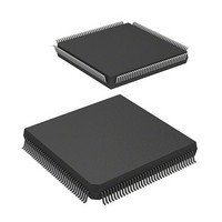
D12332VFC25
Manufacturer Part Number
D12332VFC25
Description
MCU 3V 0K 144-QFP
Manufacturer
Renesas Electronics America
Series
H8® H8S/2300r
Datasheet
1.DF2338VFC25V.pdf
(1246 pages)
Specifications of D12332VFC25
Core Processor
H8S/2000
Core Size
16-Bit
Speed
25MHz
Connectivity
SCI, SmartCard
Peripherals
DMA, POR, PWM, WDT
Number Of I /o
106
Program Memory Type
ROMless
Ram Size
8K x 8
Voltage - Supply (vcc/vdd)
2.7 V ~ 3.6 V
Data Converters
A/D 12x10b; D/A 4x8b
Oscillator Type
Internal
Operating Temperature
-20°C ~ 75°C
Package / Case
144-QFP
Lead Free Status / RoHS Status
Contains lead / RoHS non-compliant
Eeprom Size
-
Program Memory Size
-
Other names
HD6412332VFC25
HD6412332VFC25
HD6412332VFC25
Available stocks
Company
Part Number
Manufacturer
Quantity
Price
Company:

Part Number:
D12332VFC25V
Manufacturer:
Renesas Electronics America
Quantity:
10 000


Section 5 Interrupt Controller
5.6.3
Operation
The interrupt controller has three main functions in DTC and DMAC control.
Selection of Interrupt Source: With the DMAC, the activation source is input directly to each
channel. The activation source for each DMAC channel is selected with bits DTF3 to DTF0 in
DMACR. Whether the selected activation source is to be managed by the DMAC can be selected
with the DTA bit of DMABCR. When the DTA bit is set to 1, the interrupt source constituting that
DMAC activation source is not a DTC activation source or CPU interrupt source.
For interrupt sources other than interrupts managed by the DMAC, it is possible to select DTC
activation request or CPU interrupt request with the DTCE bit of DTCERA to DTCERF in the
DTC.
After a DTC data transfer, the DTCE bit can be cleared to 0 and an interrupt request sent to the
CPU in accordance with the specification of the DISEL bit of MRB in the DTC.
When the DTC has performed the specified number of data transfers and the transfer counter value
is zero, the DTCE bit is cleared to 0 and an interrupt request is sent to the CPU after the DTC data
transfer.
Determination of Priority: The DTC activation source is selected in accordance with the default
priority order, and is not affected by mask or priority levels. See section 7.6, Interrupts, and
section 8.3.3, DTC Vector Table, for the respective priorities.
With the DMAC, the activation source is input directly to each channel.
Operation Order: If the same interrupt is selected as a DTC activation source and a CPU
interrupt source, the DTC data transfer is performed first, followed by CPU interrupt exception
handling.
If the same interrupt is selected as a DMAC activation source and a DTC activation source or CPU
interrupt source, operations are performed for them independently according to their respective
operating statuses and bus mastership priorities.
Table 5.11 summarizes interrupt source selection and interrupt source clearance control according
to the settings of the DTA bit of DMABCR in the DMAC, the DTCE bit of DTCERA to DTCERF
in the DTC, and the DISEL bit of MRB in the DTC.
Rev.4.00 Sep. 07, 2007 Page 127 of 1210
REJ09B0245-0400
Related parts for D12332VFC25
Image
Part Number
Description
Manufacturer
Datasheet
Request
R

Part Number:
Description:
KIT STARTER FOR M16C/29
Manufacturer:
Renesas Electronics America
Datasheet:

Part Number:
Description:
KIT STARTER FOR R8C/2D
Manufacturer:
Renesas Electronics America
Datasheet:

Part Number:
Description:
R0K33062P STARTER KIT
Manufacturer:
Renesas Electronics America
Datasheet:

Part Number:
Description:
KIT STARTER FOR R8C/23 E8A
Manufacturer:
Renesas Electronics America
Datasheet:

Part Number:
Description:
KIT STARTER FOR R8C/25
Manufacturer:
Renesas Electronics America
Datasheet:

Part Number:
Description:
KIT STARTER H8S2456 SHARPE DSPLY
Manufacturer:
Renesas Electronics America
Datasheet:

Part Number:
Description:
KIT STARTER FOR R8C38C
Manufacturer:
Renesas Electronics America
Datasheet:

Part Number:
Description:
KIT STARTER FOR R8C35C
Manufacturer:
Renesas Electronics America
Datasheet:

Part Number:
Description:
KIT STARTER FOR R8CL3AC+LCD APPS
Manufacturer:
Renesas Electronics America
Datasheet:
Part Number:
Description:
KIT STARTER FOR RX610
Manufacturer:
Renesas Electronics America
Datasheet:

Part Number:
Description:
KIT STARTER FOR R32C/118
Manufacturer:
Renesas Electronics America
Datasheet:

Part Number:
Description:
KIT DEV RSK-R8C/26-29
Manufacturer:
Renesas Electronics America
Datasheet:

Part Number:
Description:
KIT STARTER FOR SH7124
Manufacturer:
Renesas Electronics America
Datasheet:

Part Number:
Description:
KIT STARTER FOR H8SX/1622
Manufacturer:
Renesas Electronics America
Datasheet:

Part Number:
Description:
KIT DEV FOR SH7203
Manufacturer:
Renesas Electronics America
Datasheet: