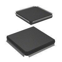
D12332VFC25 Renesas Electronics America, D12332VFC25 Datasheet - Page 320

D12332VFC25
Manufacturer Part Number
D12332VFC25
Description
MCU 3V 0K 144-QFP
Manufacturer
Renesas Electronics America
Series
H8® H8S/2300r
Datasheet
1.DF2338VFC25V.pdf
(1246 pages)
Specifications of D12332VFC25
Core Processor
H8S/2000
Core Size
16-Bit
Speed
25MHz
Connectivity
SCI, SmartCard
Peripherals
DMA, POR, PWM, WDT
Number Of I /o
106
Program Memory Type
ROMless
Ram Size
8K x 8
Voltage - Supply (vcc/vdd)
2.7 V ~ 3.6 V
Data Converters
A/D 12x10b; D/A 4x8b
Oscillator Type
Internal
Operating Temperature
-20°C ~ 75°C
Package / Case
144-QFP
Lead Free Status / RoHS Status
Contains lead / RoHS non-compliant
Eeprom Size
-
Program Memory Size
-
Other names
HD6412332VFC25
HD6412332VFC25
HD6412332VFC25
Available stocks
Company
Part Number
Manufacturer
Quantity
Price
Company:
Part Number:
D12332VFC25V
Manufacturer:
Renesas Electronics America
Quantity:
10 000
- Current page: 320 of 1246
- Download datasheet (7Mb)
7.6
The sources of interrupts generated by the DMAC are transfer end and transfer break. Table 7.14
shows the interrupt sources and their priority order.
Table 7.14 Interrupt Source Priority Order
DEND0A
DEND0B
DEND1A
DEND1B
Enabling or disabling of each interrupt source is set by means of the DTIE bit for the
corresponding channel in DMABCR, and interrupts from each source are sent to the interrupt
controller independently.
The relative priority of transfer end interrupts on each channel is decided by the interrupt
controller, as shown in table 7.14.
Figure 7.39 shows a block diagram of a transfer end/transfer break interrupt. An interrupt is
always generated when the DTIE bit is set to 1 while the DTE bit is cleared to 0.
In full address mode, a transfer break interrupt is generated when the DTME bit is cleared to 0
while the DTIEB bit is set to 1.
In both short address mode and full address mode, DMABCR should be set so as to prevent the
occurrence of a combination that constitutes a condition for interrupt generation during setting.
Rev.4.00 Sep. 07, 2007 Page 288 of 1210
REJ09B0245-0400
Interrupt
Name
Interrupts
DTE/
DTME
Figure 7.39 Block Diagram of Transfer End/Transfer Break Interrupt
DTIE
Interrupt due to end of
transfer on channel 0A
Interrupt due to end of
transfer on channel 0B
Interrupt due to end of
transfer on channel 1A
Interrupt due to end of
transfer on channel 1B
Short Address Mode
Interrupt Source
Full Address Mode
Interrupt due to end of
transfer on channel 0
Interrupt due to break in
transfer on channel 0
Interrupt due to end of
transfer on channel 1
Interrupt due to break in
transfer on channel 1
Transfer end/transfer
break interrupt
High
Low
Interrupt
Priority Order
Related parts for D12332VFC25
Image
Part Number
Description
Manufacturer
Datasheet
Request
R

Part Number:
Description:
KIT STARTER FOR M16C/29
Manufacturer:
Renesas Electronics America
Datasheet:

Part Number:
Description:
KIT STARTER FOR R8C/2D
Manufacturer:
Renesas Electronics America
Datasheet:

Part Number:
Description:
R0K33062P STARTER KIT
Manufacturer:
Renesas Electronics America
Datasheet:

Part Number:
Description:
KIT STARTER FOR R8C/23 E8A
Manufacturer:
Renesas Electronics America
Datasheet:

Part Number:
Description:
KIT STARTER FOR R8C/25
Manufacturer:
Renesas Electronics America
Datasheet:

Part Number:
Description:
KIT STARTER H8S2456 SHARPE DSPLY
Manufacturer:
Renesas Electronics America
Datasheet:

Part Number:
Description:
KIT STARTER FOR R8C38C
Manufacturer:
Renesas Electronics America
Datasheet:

Part Number:
Description:
KIT STARTER FOR R8C35C
Manufacturer:
Renesas Electronics America
Datasheet:

Part Number:
Description:
KIT STARTER FOR R8CL3AC+LCD APPS
Manufacturer:
Renesas Electronics America
Datasheet:

Part Number:
Description:
KIT STARTER FOR RX610
Manufacturer:
Renesas Electronics America
Datasheet:

Part Number:
Description:
KIT STARTER FOR R32C/118
Manufacturer:
Renesas Electronics America
Datasheet:

Part Number:
Description:
KIT DEV RSK-R8C/26-29
Manufacturer:
Renesas Electronics America
Datasheet:

Part Number:
Description:
KIT STARTER FOR SH7124
Manufacturer:
Renesas Electronics America
Datasheet:

Part Number:
Description:
KIT STARTER FOR H8SX/1622
Manufacturer:
Renesas Electronics America
Datasheet:

Part Number:
Description:
KIT DEV FOR SH7203
Manufacturer:
Renesas Electronics America
Datasheet:


