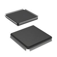
HD6417751RF240V Renesas Electronics America, HD6417751RF240V Datasheet - Page 1041

HD6417751RF240V
Manufacturer Part Number
HD6417751RF240V
Description
MPU 1.5/3.3V 0K PB-FREE 256-QFP
Manufacturer
Renesas Electronics America
Series
SuperH® SH7750r
Datasheet
1.D6417751RBP200DV.pdf
(1226 pages)
Specifications of HD6417751RF240V
Core Processor
SH-4
Core Size
32-Bit
Speed
240MHz
Connectivity
EBI/EMI, FIFO, SCI, SmartCard
Peripherals
DMA, POR, WDT
Number Of I /o
39
Program Memory Type
ROMless
Ram Size
48K x 8
Voltage - Supply (vcc/vdd)
1.4 V ~ 1.6 V
Oscillator Type
External
Operating Temperature
-20°C ~ 75°C
Package / Case
256-QFP Exposed Pad, 256-eQFP, 256-HQFP
Lead Free Status / RoHS Status
Lead free / RoHS Compliant
Eeprom Size
-
Program Memory Size
-
Data Converters
-
Available stocks
Company
Part Number
Manufacturer
Quantity
Price
Company:
Part Number:
HD6417751RF240V
Manufacturer:
Renesas Electronics America
Quantity:
10 000
- Current page: 1041 of 1226
- Download datasheet (7Mb)
22. PCI Controller (PCIC)
In DMA transfers, all transferred data is handled in long word units, so the number of transfer
bytes and the low 2 bits of the transfer initial address are ignored and B'0000 is always output for
BE[3:0]. Also, in DMA transfers, because burst transfers are effected using linear addressing, the
low 2 bits of the output PCI address are always B'00.
Note that locked transfers are not supported in the case of DMA transfers.
Starting DMA Transfer: The following registers exist to control DMA transfers: PCI DMA
transfer arbitration register (PCIDMABT) and, for four channels, the PCI DMA transfer PCI
address register [3:0] (PCIDPA [3:0]), PCI DMA transfer local bus starting address register [3:0]
(PCIDLA [3:0]), PCI DMA transfer count register [3:0] (PCIDTC [3:0]), and PCI DMA control
register [3:0] (PCIDCR [3:0]).
Set the arbitration mode in PCIDMABT prior to starting the DMA transfer. Also select the DMA
channel to be used, set the PCI bus starting address and local bus starting address in the
appropriate PCIDPA and PCIDLA for the selected channel, respectively, set the number of bytes
in the transfer in PCIDTC, set the DMA transfer mode in the PCIDCR, and specify a transfer start
request.
The transfer starting address and the number of bytes in the transfer can be set on byte or word
boundaries, but because the least significant two bits of these registers are ignored, the transfer is
performed in longword units. Also, note that the local bus starting address set in PCIDLA is the
physical address.
PCIDPA, PCIDLA, and PCIDTC are updated during data transfer. If another DMA transfer is to
be performed on completion of one DMA transfer, new values must be set in these registers.
The registers controlling DMA transfers can be set from both CPU and PCI device. Note that the
DMA channel allocated to the CPU and PCI device must be predetermined when configuring the
system.
When performing DMA transfers, the address of the local bus and the size of data to be transferred
can be set to a 32-byte boundary to ensure that data transfers on the local bus are as efficient as
possible.
PCIDCR can be used to control the abortion of DMA transfers, the direction of DMA transfers, to
select PCI commands (memory/I/O) whether to update the PCI address, whether to update the
local address, whether to use transfer termination interrupts, and, when the local bus is big endian,
the method of alignment.
Figure 22.5 shows an example of DMA transfer control register settings.
Rev.4.00 Oct. 10, 2008 Page 941 of 1122
REJ09B0370-0400
Related parts for HD6417751RF240V
Image
Part Number
Description
Manufacturer
Datasheet
Request
R

Part Number:
Description:
KIT STARTER FOR M16C/29
Manufacturer:
Renesas Electronics America
Datasheet:

Part Number:
Description:
KIT STARTER FOR R8C/2D
Manufacturer:
Renesas Electronics America
Datasheet:

Part Number:
Description:
R0K33062P STARTER KIT
Manufacturer:
Renesas Electronics America
Datasheet:

Part Number:
Description:
KIT STARTER FOR R8C/23 E8A
Manufacturer:
Renesas Electronics America
Datasheet:

Part Number:
Description:
KIT STARTER FOR R8C/25
Manufacturer:
Renesas Electronics America
Datasheet:

Part Number:
Description:
KIT STARTER H8S2456 SHARPE DSPLY
Manufacturer:
Renesas Electronics America
Datasheet:

Part Number:
Description:
KIT STARTER FOR R8C38C
Manufacturer:
Renesas Electronics America
Datasheet:

Part Number:
Description:
KIT STARTER FOR R8C35C
Manufacturer:
Renesas Electronics America
Datasheet:

Part Number:
Description:
KIT STARTER FOR R8CL3AC+LCD APPS
Manufacturer:
Renesas Electronics America
Datasheet:

Part Number:
Description:
KIT STARTER FOR RX610
Manufacturer:
Renesas Electronics America
Datasheet:

Part Number:
Description:
KIT STARTER FOR R32C/118
Manufacturer:
Renesas Electronics America
Datasheet:

Part Number:
Description:
KIT DEV RSK-R8C/26-29
Manufacturer:
Renesas Electronics America
Datasheet:

Part Number:
Description:
KIT STARTER FOR SH7124
Manufacturer:
Renesas Electronics America
Datasheet:

Part Number:
Description:
KIT STARTER FOR H8SX/1622
Manufacturer:
Renesas Electronics America
Datasheet:

Part Number:
Description:
KIT DEV FOR SH7203
Manufacturer:
Renesas Electronics America
Datasheet:


