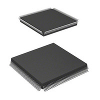
HD64F7051SFJ20V Renesas Electronics America, HD64F7051SFJ20V Datasheet - Page 100

HD64F7051SFJ20V
Manufacturer Part Number
HD64F7051SFJ20V
Description
MCU 5V 256K J-TEMP PB-FREE QFP-1
Manufacturer
Renesas Electronics America
Series
SuperH® SH7050r
Datasheet
1.HD64F7050SFJ20V.pdf
(843 pages)
Specifications of HD64F7051SFJ20V
Core Processor
SH-2
Core Size
32-Bit
Speed
20MHz
Connectivity
EBI/EMI, SCI
Peripherals
DMA, WDT
Number Of I /o
102
Program Memory Size
256KB (256K x 8)
Program Memory Type
FLASH
Ram Size
10K x 8
Voltage - Supply (vcc/vdd)
4.5 V ~ 5.5 V
Data Converters
A/D 16x10b
Oscillator Type
Internal
Operating Temperature
-40°C ~ 85°C
Package / Case
168-QFP
Lead Free Status / RoHS Status
Lead free / RoHS Compliant
Eeprom Size
-
Available stocks
Company
Part Number
Manufacturer
Quantity
Price
Company:
Part Number:
HD64F7051SFJ20V
Manufacturer:
RENESAS
Quantity:
101
Part Number:
HD64F7051SFJ20V
Manufacturer:
RENESAS/瑞萨
Quantity:
20 000
- Current page: 100 of 843
- Download datasheet (5Mb)
Section 6 Interrupt Controller (INTC)
6.2
There are four types of interrupt sources: NMI, user breaks, IRQ, and on-chip peripheral modules.
Each interrupt has a priority expressed as a priority level (0 to 16, with 0 the lowest and 16 the
highest). Giving an interrupt a priority level of 0 masks it.
6.2.1
The NMI interrupt has priority 16 and is always accepted. Input at the NMI pin is detected by
edge. Use the NMI edge select bit (NMIE) in the interrupt control register (ICR) to select either
the rising or falling edge. NMI interrupt exception processing sets the interrupt mask level bits
(I3–I0) in the status register (SR) to level 15.
6.2.2
A user break interrupt has a priority of level 15, and occurs when the break condition set in the
user break controller (UBC) is satisfied. User break interrupt requests are detected by edge and are
held until accepted. User break interrupt exception processing sets the interrupt mask level bits
(I3–I0) in the status register (SR) to level 15. For more information about the user break interrupt,
see Section 7, User Break Controller.
6.2.3
IRQ interrupts are requested by input from pins IRQ0–IRQ7. Set the IRQ sense select bits
(IRQ0S–IRQ7S) of the interrupt control register (ICR) to select low level detection or falling edge
detection for each pin. The priority level can be set from 0 to 15 for each pin using the interrupt
priority registers A and B (IPRA–IPRB).
When IRQ interrupts are set to low level detection, an interrupt request signal is sent to the INTC
during the period the IRQ pin is low level. Interrupt request signals are not sent to the INTC when
the IRQ pin becomes high level. Interrupt request levels can be confirmed by reading the IRQ
flags (IRQ0F–IRQ7F) of the IRQ status register (ISR).
When IRQ interrupts are set to falling edge detection, interrupt request signals are sent to the
INTC upon detecting a change on the IRQ pin from high to low level. IRQ interrupt request
detection results are maintained until the interrupt request is accepted. Confirmation that IRQ
interrupt requests have been detected is possible by reading the IRQ flags (IRQ0F–IRQ7F) of the
IRQ status register (ISR), and by writing a 0 after reading a 1, IRQ interrupt request detection
results can be withdrawn.
Rev. 5.00 Jan 06, 2006 page 78 of 818
REJ09B0273-0500
Interrupt Sources
NMI Interrupts
User Break Interrupt
IRQ Interrupts
Related parts for HD64F7051SFJ20V
Image
Part Number
Description
Manufacturer
Datasheet
Request
R

Part Number:
Description:
KIT STARTER FOR M16C/29
Manufacturer:
Renesas Electronics America
Datasheet:

Part Number:
Description:
KIT STARTER FOR R8C/2D
Manufacturer:
Renesas Electronics America
Datasheet:

Part Number:
Description:
R0K33062P STARTER KIT
Manufacturer:
Renesas Electronics America
Datasheet:

Part Number:
Description:
KIT STARTER FOR R8C/23 E8A
Manufacturer:
Renesas Electronics America
Datasheet:

Part Number:
Description:
KIT STARTER FOR R8C/25
Manufacturer:
Renesas Electronics America
Datasheet:

Part Number:
Description:
KIT STARTER H8S2456 SHARPE DSPLY
Manufacturer:
Renesas Electronics America
Datasheet:

Part Number:
Description:
KIT STARTER FOR R8C38C
Manufacturer:
Renesas Electronics America
Datasheet:

Part Number:
Description:
KIT STARTER FOR R8C35C
Manufacturer:
Renesas Electronics America
Datasheet:

Part Number:
Description:
KIT STARTER FOR R8CL3AC+LCD APPS
Manufacturer:
Renesas Electronics America
Datasheet:

Part Number:
Description:
KIT STARTER FOR RX610
Manufacturer:
Renesas Electronics America
Datasheet:

Part Number:
Description:
KIT STARTER FOR R32C/118
Manufacturer:
Renesas Electronics America
Datasheet:

Part Number:
Description:
KIT DEV RSK-R8C/26-29
Manufacturer:
Renesas Electronics America
Datasheet:

Part Number:
Description:
KIT STARTER FOR SH7124
Manufacturer:
Renesas Electronics America
Datasheet:

Part Number:
Description:
KIT STARTER FOR H8SX/1622
Manufacturer:
Renesas Electronics America
Datasheet:

Part Number:
Description:
KIT DEV FOR SH7203
Manufacturer:
Renesas Electronics America
Datasheet:


