HD64F7051SFJ20V Renesas Electronics America, HD64F7051SFJ20V Datasheet - Page 445
HD64F7051SFJ20V
Manufacturer Part Number
HD64F7051SFJ20V
Description
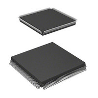
MCU 5V 256K J-TEMP PB-FREE QFP-1
Manufacturer
Renesas Electronics America
Series
SuperH® SH7050r
Datasheet
1.HD64F7050SFJ20V.pdf
(843 pages)
Specifications of HD64F7051SFJ20V
Core Processor
SH-2
Core Size
32-Bit
Speed
20MHz
Connectivity
EBI/EMI, SCI
Peripherals
DMA, WDT
Number Of I /o
102
Program Memory Size
256KB (256K x 8)
Program Memory Type
FLASH
Ram Size
10K x 8
Voltage - Supply (vcc/vdd)
4.5 V ~ 5.5 V
Data Converters
A/D 16x10b
Oscillator Type
Internal
Operating Temperature
-40°C ~ 85°C
Package / Case
168-QFP
Lead Free Status / RoHS Status
Lead free / RoHS Compliant
Eeprom Size
-
Available stocks
Company
Part Number
Manufacturer
Quantity
Price
Company:

Part Number:
HD64F7051SFJ20V
Manufacturer:
RENESAS
Quantity:
101
Part Number:
HD64F7051SFJ20V
Manufacturer:
RENESAS/瑞萨
Quantity:
20 000


3. After setting RDRF to 1, if the receive-data-full interrupt enable bit (RIE) is set to 1 in the
Transmitting and Receiving Serial Data Simultaneously (Clock Synchronous Mode): Figure
13.22 shows a sample flowchart for transmitting and receiving serial data simultaneously. The
procedure is as follows (the steps correspond to the numbers in the flowchart):
1. SCI initialization: Set the TxD and RxD pins using the PFC.
2. SCI status check and transmit data write: Read the serial status register (SSR), check that the
3. Receive error handling: If a receive error occurs, read the ORER bit in SSR to identify the
4. SCI status check and receive data read: Read the serial status register (SSR), check that RDRF
5. Continue transmitting and receiving serial data: Read the RDRF bit and RDR, and clear RDRF
Note: When selecting the transmission or receiving mode to the simultaneous transmission and
RDR. If this check passes, the SCI sets RDRF to 1 and stores the received data in the RDR. If
the check does not pass (receive error), the SCI operates as indicated in table 13.11 and no
further transmission or reception is possible. If the error flag is set to 1, the RDRF bit is not set
to 1 during reception, even if the RDRF bit is 0 cleared. When restarting reception, be sure to
clear the error flag.
SCR, the SCI requests a receive-data-full interrupt (RxI). If the ORER bit is set to 1 and the
receive-data-full interrupt enable bit (RIE) in the SCR is also set to 1, the SCI requests a
receive-error interrupt (ERI).
TDRE bit is 1, then write transmit data in the transmit data register (TDR) and clear TDRE to
0. The TxI interrupt can also be used to determine if the TDRE bit has changed from 0 to 1.
error. After executing the necessary error processing, clear ORER to 0. Transmitting/receiving
cannot resume if ORER remains set to 1.
is set to 1, then read receive data from the receive data register (RDR) and clear RDRF to 0.
The RxI interrupt can also be used to determine if the RDRF bit has changed from 0 to 1.
to 0 before the frame MSB (bit 7) of the current frame is received. Also read the TDRE bit to
check whether it is safe to write (if it reads 1); if so, write data in TDR, then clear TDRE to 0
before the MSB (bit 7) of the current frame is transmitted. When the DMAC or the DTC is
started by a transmit-data-empty interrupt request (TxI) to write data in TDR, the TDRE bit is
checked and cleared automatically. When the DMAC is started by a receive-data-full interrupt
(RxI) to read RDR, the RDRF bit is cleared automatically.
receiving mode, clear TE and RE bits to zero once, then set both of them to 1
simultaneously.
Section 13 Serial Communication Interface (SCI)
Rev. 5.00 Jan 06, 2006 page 423 of 818
REJ09B0273-0500
Related parts for HD64F7051SFJ20V
Image
Part Number
Description
Manufacturer
Datasheet
Request
R

Part Number:
Description:
KIT STARTER FOR M16C/29
Manufacturer:
Renesas Electronics America
Datasheet:

Part Number:
Description:
KIT STARTER FOR R8C/2D
Manufacturer:
Renesas Electronics America
Datasheet:

Part Number:
Description:
R0K33062P STARTER KIT
Manufacturer:
Renesas Electronics America
Datasheet:

Part Number:
Description:
KIT STARTER FOR R8C/23 E8A
Manufacturer:
Renesas Electronics America
Datasheet:

Part Number:
Description:
KIT STARTER FOR R8C/25
Manufacturer:
Renesas Electronics America
Datasheet:

Part Number:
Description:
KIT STARTER H8S2456 SHARPE DSPLY
Manufacturer:
Renesas Electronics America
Datasheet:

Part Number:
Description:
KIT STARTER FOR R8C38C
Manufacturer:
Renesas Electronics America
Datasheet:

Part Number:
Description:
KIT STARTER FOR R8C35C
Manufacturer:
Renesas Electronics America
Datasheet:

Part Number:
Description:
KIT STARTER FOR R8CL3AC+LCD APPS
Manufacturer:
Renesas Electronics America
Datasheet:
Part Number:
Description:
KIT STARTER FOR RX610
Manufacturer:
Renesas Electronics America
Datasheet:

Part Number:
Description:
KIT STARTER FOR R32C/118
Manufacturer:
Renesas Electronics America
Datasheet:

Part Number:
Description:
KIT DEV RSK-R8C/26-29
Manufacturer:
Renesas Electronics America
Datasheet:

Part Number:
Description:
KIT STARTER FOR SH7124
Manufacturer:
Renesas Electronics America
Datasheet:

Part Number:
Description:
KIT STARTER FOR H8SX/1622
Manufacturer:
Renesas Electronics America
Datasheet:

Part Number:
Description:
KIT DEV FOR SH7203
Manufacturer:
Renesas Electronics America
Datasheet: