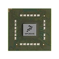
MPC8544DS Freescale Semiconductor, MPC8544DS Datasheet - Page 12

MPC8544DS
Manufacturer Part Number
MPC8544DS
Description
BOARD DEVELOPMENT SYSTEM 8544
Manufacturer
Freescale Semiconductor
Series
PowerQUICC III™r
Type
MPUr
Datasheets
1.MPC8544VTALF.pdf
(117 pages)
2.MPC8544VTALF.pdf
(2 pages)
3.MPC8544VTALF.pdf
(1340 pages)
4.MPC8544DS.pdf
(2 pages)
Specifications of MPC8544DS
Contents
Board
Processor To Be Evaluated
MPC8544E
Data Bus Width
32 bit
Interface Type
Ethernet, I2C
Operating Supply Voltage
- 0.3 V to + 1.1 V
Leaded Process Compatible
Yes
Peak Reflow Compatible (260 C)
Yes
Rohs Compliant
Yes
For Use With/related Products
MPC8544
For Use With
PPC8544EVTANG - EVAL MPC8544 783FCPBGA
Lead Free Status / RoHS Status
Lead free / RoHS Compliant
- MPC8544VTALF PDF datasheet
- MPC8544VTALF PDF datasheet #2
- MPC8544VTALF PDF datasheet #3
- MPC8544DS PDF datasheet #4
- Current page: 12 of 1340
- Download datasheet (12Mb)
Paragraph
Number
7.3.1.2.3
7.3.1.3
7.3.1.3.1
7.3.1.3.2
7.3.1.4
7.3.1.4.1
7.3.1.4.2
7.4
7.4.1
7.5
7.6
7.6.1
7.6.2
7.7
7.7.1
7.7.2
7.7.3
7.7.4
7.7.5
7.7.6
7.8
7.8.1
7.8.2
7.9
7.9.1
7.9.1.1
7.9.1.2
7.9.2
7.9.3
7.9.3.1
7.9.3.2
7.9.4
7.9.5
7.9.6
xii
MPC8544E PowerQUICC III Integrated Host Processor Family Reference Manual, Rev. 1
External Writes to the L2 Cache (Cache Stashing)........................................................ 7-25
L2 Cache Timing ........................................................................................................... 7-27
L2 Cache and SRAM Coherency................................................................................... 7-27
L2 Cache Locking.......................................................................................................... 7-29
PLRU L2 Replacement Policy....................................................................................... 7-31
L2 Cache Operation ....................................................................................................... 7-33
Stash-Only Cache Regions ........................................................................................ 7-26
L2 Cache Coherency Rules........................................................................................ 7-28
Memory-Mapped SRAM Coherency Rules .............................................................. 7-29
Locking the Entire L2 Cache ..................................................................................... 7-29
Locking Programmed Memory Ranges..................................................................... 7-30
Locking Selected Lines.............................................................................................. 7-30
Clearing Locks on Selected Lines ............................................................................. 7-30
Flash Clearing of Instruction and Data Locks ........................................................... 7-31
Locks with Stale Data ................................................................................................ 7-31
PLRU Bit Update Considerations.............................................................................. 7-32
Allocation of Lines .................................................................................................... 7-32
Initialization ............................................................................................................... 7-33
Flash Invalidation of the L2 Cache............................................................................ 7-34
Managing Errors ........................................................................................................ 7-34
L2 Cache States ......................................................................................................... 7-34
L2 State Transitions ................................................................................................... 7-35
Error Checking and Correcting (ECC) ...................................................................... 7-39
L2 Memory-Mapped SRAM Registers ................................................................. 7-15
L2 Error Registers.................................................................................................. 7-17
L2 Cache Initialization .......................................................................................... 7-33
Memory-Mapped SRAM Initialization ................................................................. 7-33
ECC Errors............................................................................................................. 7-34
Tag Parity Errors.................................................................................................... 7-34
L2 Cache External Write Control Registers 0–3 (L2CEWCRn)....................... 7-14
L2 Memory-Mapped SRAM Base Address Registers 0–1 (L2SRBARn) ........ 7-16
L2 Memory-Mapped SRAM Base Address Registers Extended Address 0–1
Error Injection Registers.................................................................................... 7-18
Error Control and Capture Registers ................................................................. 7-20
(L2SRBAREAn)............................................................................................ 7-17
Contents
Title
Freescale Semiconductor
Number
Page
Related parts for MPC8544DS
Image
Part Number
Description
Manufacturer
Datasheet
Request
R
Part Number:
Description:
Manufacturer:
Freescale Semiconductor, Inc
Datasheet:
Part Number:
Description:
Manufacturer:
Freescale Semiconductor, Inc
Datasheet:
Part Number:
Description:
Manufacturer:
Freescale Semiconductor, Inc
Datasheet:
Part Number:
Description:
Manufacturer:
Freescale Semiconductor, Inc
Datasheet:
Part Number:
Description:
Manufacturer:
Freescale Semiconductor, Inc
Datasheet:
Part Number:
Description:
Manufacturer:
Freescale Semiconductor, Inc
Datasheet:
Part Number:
Description:
Manufacturer:
Freescale Semiconductor, Inc
Datasheet:
Part Number:
Description:
Manufacturer:
Freescale Semiconductor, Inc
Datasheet:
Part Number:
Description:
Manufacturer:
Freescale Semiconductor, Inc
Datasheet:
Part Number:
Description:
Manufacturer:
Freescale Semiconductor, Inc
Datasheet:
Part Number:
Description:
Manufacturer:
Freescale Semiconductor, Inc
Datasheet:
Part Number:
Description:
Manufacturer:
Freescale Semiconductor, Inc
Datasheet:
Part Number:
Description:
Manufacturer:
Freescale Semiconductor, Inc
Datasheet:
Part Number:
Description:
Manufacturer:
Freescale Semiconductor, Inc
Datasheet:
Part Number:
Description:
Manufacturer:
Freescale Semiconductor, Inc
Datasheet:


