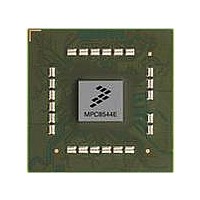
MPC8544DS Freescale Semiconductor, MPC8544DS Datasheet - Page 23

MPC8544DS
Manufacturer Part Number
MPC8544DS
Description
BOARD DEVELOPMENT SYSTEM 8544
Manufacturer
Freescale Semiconductor
Series
PowerQUICC III™r
Type
MPUr
Datasheets
1.MPC8544VTALF.pdf
(117 pages)
2.MPC8544VTALF.pdf
(2 pages)
3.MPC8544VTALF.pdf
(1340 pages)
4.MPC8544DS.pdf
(2 pages)
Specifications of MPC8544DS
Contents
Board
Processor To Be Evaluated
MPC8544E
Data Bus Width
32 bit
Interface Type
Ethernet, I2C
Operating Supply Voltage
- 0.3 V to + 1.1 V
Leaded Process Compatible
Yes
Peak Reflow Compatible (260 C)
Yes
Rohs Compliant
Yes
For Use With/related Products
MPC8544
For Use With
PPC8544EVTANG - EVAL MPC8544 783FCPBGA
Lead Free Status / RoHS Status
Lead free / RoHS Compliant
- MPC8544VTALF PDF datasheet
- MPC8544VTALF PDF datasheet #2
- MPC8544VTALF PDF datasheet #3
- MPC8544DS PDF datasheet #4
- Current page: 23 of 1340
- Download datasheet (12Mb)
Paragraph
Number
13.3.1.2
13.3.1.3
13.3.1.4
13.3.1.5
13.3.1.6
13.3.1.7
13.3.1.8
13.3.1.9
13.3.1.10
13.3.1.11
13.3.1.12
13.3.1.13
13.4
13.4.1
13.4.1.1
13.4.1.2
13.4.1.3
13.4.1.4
13.4.2
13.4.3
13.4.4
13.4.4.1
13.4.4.2
13.4.4.3
13.4.5
13.4.5.1
13.4.5.2
13.4.5.3
13.5
14.1
14.1.1
14.1.2
14.1.3
14.1.3.1
14.1.3.2
14.1.4
Freescale Semiconductor
MPC8544E PowerQUICC III Integrated Host Processor Family Reference Manual, Rev. 1
Functional Description................................................................................................. 13-19
DUART Initialization/Application Information .......................................................... 13-24
Introduction.................................................................................................................... 14-1
Serial Interface......................................................................................................... 13-20
Baud-Rate Generator Logic ..................................................................................... 13-21
Local Loopback Mode ............................................................................................. 13-22
Errors ....................................................................................................................... 13-22
FIFO Mode .............................................................................................................. 13-22
Overview.................................................................................................................... 14-2
Features...................................................................................................................... 14-2
Modes of Operation ................................................................................................... 14-3
Power-Down Mode.................................................................................................... 14-4
Transmitter Holding Registers (UTHR0, UTHR1) (ULCR[DLAB] = 0) ............. 13-6
Divisor Most and Least Significant Byte Registers (UDMB and UDLB)
Interrupt Enable Register (UIER) (ULCR[DLAB] = 0)........................................ 13-9
Interrupt ID Registers (UIIR0, UIIR1) (ULCR[DLAB] = 0) ................................ 13-9
FIFO Control Registers (UFCR0, UFCR1) (ULCR[DLAB] = 0)....................... 13-11
Line Control Registers (ULCR0, ULCR1).......................................................... 13-12
Modem Control Registers (UMCR0, UMCR1)................................................... 13-14
Line Status Registers (ULSR0, ULSR1) ............................................................. 13-15
Modem Status Registers (UMSR0, UMSR1) ...................................................... 13-16
Scratch Registers (USCR0, USCR1) ................................................................... 13-17
Alternate Function Registers (UAFR0, UAFR1) (ULCR[DLAB] = 1) .............. 13-17
DMA Status Registers (UDSR0, UDSR1) .......................................................... 13-18
START Bit ........................................................................................................... 13-20
Data Transfer ....................................................................................................... 13-21
Parity Bit .............................................................................................................. 13-21
STOP Bit.............................................................................................................. 13-21
Framing Error ...................................................................................................... 13-22
Parity Error .......................................................................................................... 13-22
Overrun Error....................................................................................................... 13-22
FIFO Interrupts .................................................................................................... 13-23
DMA Mode Select ............................................................................................... 13-23
Interrupt Control Logic........................................................................................ 13-23
LBC Bus Clock and Clock Ratios ......................................................................... 14-3
Source ID Debug Mode ......................................................................................... 14-4
(ULCR[DLAB] = 1) .......................................................................................... 13-7
Local Bus Controller
Contents
Chapter 14
Title
Number
Page
xxiii
Related parts for MPC8544DS
Image
Part Number
Description
Manufacturer
Datasheet
Request
R
Part Number:
Description:
Manufacturer:
Freescale Semiconductor, Inc
Datasheet:
Part Number:
Description:
Manufacturer:
Freescale Semiconductor, Inc
Datasheet:
Part Number:
Description:
Manufacturer:
Freescale Semiconductor, Inc
Datasheet:
Part Number:
Description:
Manufacturer:
Freescale Semiconductor, Inc
Datasheet:
Part Number:
Description:
Manufacturer:
Freescale Semiconductor, Inc
Datasheet:
Part Number:
Description:
Manufacturer:
Freescale Semiconductor, Inc
Datasheet:
Part Number:
Description:
Manufacturer:
Freescale Semiconductor, Inc
Datasheet:
Part Number:
Description:
Manufacturer:
Freescale Semiconductor, Inc
Datasheet:
Part Number:
Description:
Manufacturer:
Freescale Semiconductor, Inc
Datasheet:
Part Number:
Description:
Manufacturer:
Freescale Semiconductor, Inc
Datasheet:
Part Number:
Description:
Manufacturer:
Freescale Semiconductor, Inc
Datasheet:
Part Number:
Description:
Manufacturer:
Freescale Semiconductor, Inc
Datasheet:
Part Number:
Description:
Manufacturer:
Freescale Semiconductor, Inc
Datasheet:
Part Number:
Description:
Manufacturer:
Freescale Semiconductor, Inc
Datasheet:
Part Number:
Description:
Manufacturer:
Freescale Semiconductor, Inc
Datasheet:


