ATSAM3U-EK Atmel, ATSAM3U-EK Datasheet - Page 1021
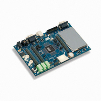
ATSAM3U-EK
Manufacturer Part Number
ATSAM3U-EK
Description
KIT EVAL FOR AT91SAM3U CORTEX
Manufacturer
Atmel
Type
MCUr
Datasheets
1.ATSAM3U-EK.pdf
(2 pages)
2.ATSAM3U-EK.pdf
(61 pages)
3.ATSAM3U-EK.pdf
(1171 pages)
4.ATSAM3U-EK.pdf
(53 pages)
Specifications of ATSAM3U-EK
Contents
Board
Processor To Be Evaluated
SAM3U
Data Bus Width
32 bit
Interface Type
RS-232, USB
Operating Supply Voltage
3 V
Silicon Manufacturer
Atmel
Core Architecture
ARM
Core Sub-architecture
Cortex - M3
Silicon Core Number
SAM3U4E
Silicon Family Name
SAM3U
Kit Contents
Board CD Docs
Rohs Compliant
Yes
For Use With/related Products
AT91SAM3U
Lead Free Status / RoHS Status
Lead free / RoHS Compliant
Available stocks
Company
Part Number
Manufacturer
Quantity
Price
Company:

Part Number:
ATSAM3U-EK
Manufacturer:
Atmel
Quantity:
10


40.3.5
40.3.5.1
40.3.5.2
6430D–ATARM–25-Mar-11
Programming a Channel
Programming Examples
Single-buffer Transfer (Row 1)
Four registers, the DMAC_DSCRx, the DMAC_CTRLAx, the DMAC_CTRLBx and
DMAC_CFGx, need to be programmed to set up whether single or multi-buffer transfers take
place, and which type of multi-buffer transfer is used. The different transfer types are shown in
Table 40-1 on page
The “BTSIZE, SADDR and DADDR” columns indicate where the values of DMAC_SARx,
DMAC_DARx, DMAC_CTLx, and DMAC_LLPx are obtained for the next buffer transfer when
multi-buffer DMAC transfers are enabled.
1. Read the Channel Handler Status Register DMAC_CHSR.ENABLE Field to choose a
2. Clear any pending interrupts on the channel from the previous DMAC transfer by read-
3. Program the following channel registers:
free (disabled) channel.
ing the interrupt status register, DMAC_EBCISR.
a. Write the starting source address in the DMAC_SADDRx register for channel x.
b. Write the starting destination address in the DMAC_DADDRx register for channel
c. Program DMAC_CTRLAx, DMAC_CTRLBx and DMAC_CFGx according to Row 1
d. Write the control information for the DMAC transfer in the DMAC_CTRLAx and
– i. Set up the transfer type (memory or non-memory peripheral for source and
– ii. Set up the transfer characteristics, such as:
e. Write the channel configuration information into the DMAC_CFGx register for chan-
– i. Designate the handshaking interface type (hardware or software) for the source
– ii. If the hardware handshaking interface is activated for the source or destination
destination) and flow control device by programming the FC of the DMAC_CTRLBx
register.
and destination peripherals. This is not required for memory. This step requires
programming the SRC_H2SEL/DST_H2SEL bits, respectively. Writing a ‘1’ activates
the hardware handshaking interface to handle source/destination requests. Writing a
‘0’ activates the software handshaking interface to handle source/destination
requests.
peripheral, assign a handshaking interface to the source and destination peripheral.
This requires programming the SRC_PER and DST_PER bits, respectively.
– Transfer width for the source in the SRC_WIDTH field.
– Transfer width for the destination in the DST_WIDTH field.
– Incrementing/decrementing or fixed address for source in SRC_INC field.
– Incrementing/decrementing or fixed address for destination in DST_INC field.
x.
as shown in
both DST_DSCR and SRC_DSCR fields set to one.
DMAC_CTRLBx registers for channel x. For example, in the register, you can pro-
gram the following:
nel x.
1020.
Table 40-1 on page
1020. Program the DMAC_CTRLBx register with
SAM3U Series
1021
Related parts for ATSAM3U-EK
Image
Part Number
Description
Manufacturer
Datasheet
Request
R

Part Number:
Description:
AT91 ARM Thumb-based Microcontrollers
Manufacturer:
ATMEL [ATMEL Corporation]
Datasheet:

Part Number:
Description:
DEV KIT FOR AVR/AVR32
Manufacturer:
Atmel
Datasheet:

Part Number:
Description:
INTERVAL AND WIPE/WASH WIPER CONTROL IC WITH DELAY
Manufacturer:
ATMEL Corporation
Datasheet:
Part Number:
Description:
Low-Voltage Voice-Switched IC for Hands-Free Operation
Manufacturer:
ATMEL Corporation
Datasheet:
Part Number:
Description:
MONOLITHIC INTEGRATED FEATUREPHONE CIRCUIT
Manufacturer:
ATMEL Corporation
Datasheet:
Part Number:
Description:
AM-FM Receiver IC U4255BM-M
Manufacturer:
ATMEL Corporation
Datasheet:
Part Number:
Description:
Monolithic Integrated Feature Phone Circuit
Manufacturer:
ATMEL Corporation
Datasheet:
Part Number:
Description:
Multistandard Video-IF and Quasi Parallel Sound Processing
Manufacturer:
ATMEL Corporation
Datasheet:
Part Number:
Description:
High-performance EE PLD
Manufacturer:
ATMEL Corporation
Datasheet:
Part Number:
Description:
8-bit Flash Microcontroller
Manufacturer:
ATMEL Corporation
Datasheet:
Part Number:
Description:
2-Wire Serial EEPROM
Manufacturer:
ATMEL Corporation
Datasheet: