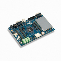
ATSAM3U-EK Atmel, ATSAM3U-EK Datasheet - Page 666

ATSAM3U-EK
Manufacturer Part Number
ATSAM3U-EK
Description
KIT EVAL FOR AT91SAM3U CORTEX
Manufacturer
Atmel
Type
MCUr
Datasheets
1.ATSAM3U-EK.pdf
(2 pages)
2.ATSAM3U-EK.pdf
(61 pages)
3.ATSAM3U-EK.pdf
(1171 pages)
4.ATSAM3U-EK.pdf
(53 pages)
Specifications of ATSAM3U-EK
Contents
Board
Processor To Be Evaluated
SAM3U
Data Bus Width
32 bit
Interface Type
RS-232, USB
Operating Supply Voltage
3 V
Silicon Manufacturer
Atmel
Core Architecture
ARM
Core Sub-architecture
Cortex - M3
Silicon Core Number
SAM3U4E
Silicon Family Name
SAM3U
Kit Contents
Board CD Docs
Rohs Compliant
Yes
For Use With/related Products
AT91SAM3U
Lead Free Status / RoHS Status
Lead free / RoHS Compliant
Available stocks
Company
Part Number
Manufacturer
Quantity
Price
Company:
Part Number:
ATSAM3U-EK
Manufacturer:
Atmel
Quantity:
10
- ATSAM3U-EK PDF datasheet
- ATSAM3U-EK PDF datasheet #2
- ATSAM3U-EK PDF datasheet #3
- ATSAM3U-EK PDF datasheet #4
- Current page: 666 of 1171
- Download datasheet (25Mb)
34.3
34.3.1
34.3.2
34.3.3
34.4
34.4.1
666
Product Dependencies
UART Operations
SAM3U Series
I/O Lines
Power Management
Interrupt Source
Baud Rate Generator
The UART pins are multiplexed with PIO lines. The programmer must first configure the corre-
sponding PIO Controller to enable I/O line operations of the UART.
Table 34-2.
The UART clock is controllable through the Power Management Controller. In this case, the pro-
grammer must first configure the PMC to enable the UART clock. Usually, the peripheral
identifier used for this purpose is 1.
The UART interrupt line is connected to one of the interrupt sources of the Nested Vectored
Interrupt Controller (NVIC). Interrupt handling requires programming of the NVIC before config-
uring the UART.
The UART operates in asynchronous mode only and supports only 8-bit character handling (with
parity). It has no clock pin.
The UART is made up of a receiver and a transmitter that operate independently, and a common
baud rate generator. Receiver timeout and transmitter time guard are not implemented. How-
ever, all the implemented features are compatible with those of a standard USART.
The baud rate generator provides the bit period clock named baud rate clock to both the receiver
and the transmitter.
The baud rate clock is the master clock divided by 16 times the value (CD) written in
UART_BRGR (Baud Rate Generator Register). If UART_BRGR is set to 0, the baud rate clock is
disabled and the UART remains inactive. The maximum allowable baud rate is Master Clock
divided by 16. The minimum allowable baud rate is Master Clock divided by (16 x 65536).
Instance
UART
UART
I/O Lines
Baud Rate
=
----------------------- -
16
Signal
URXD
UTXD
MCK
×
CD
I/O Line
PA11
PA12
Peripheral
6430D–ATARM–25-Mar-11
A
A
Related parts for ATSAM3U-EK
Image
Part Number
Description
Manufacturer
Datasheet
Request
R

Part Number:
Description:
AT91 ARM Thumb-based Microcontrollers
Manufacturer:
ATMEL [ATMEL Corporation]
Datasheet:

Part Number:
Description:
DEV KIT FOR AVR/AVR32
Manufacturer:
Atmel
Datasheet:

Part Number:
Description:
INTERVAL AND WIPE/WASH WIPER CONTROL IC WITH DELAY
Manufacturer:
ATMEL Corporation
Datasheet:

Part Number:
Description:
Low-Voltage Voice-Switched IC for Hands-Free Operation
Manufacturer:
ATMEL Corporation
Datasheet:

Part Number:
Description:
MONOLITHIC INTEGRATED FEATUREPHONE CIRCUIT
Manufacturer:
ATMEL Corporation
Datasheet:

Part Number:
Description:
AM-FM Receiver IC U4255BM-M
Manufacturer:
ATMEL Corporation
Datasheet:

Part Number:
Description:
Monolithic Integrated Feature Phone Circuit
Manufacturer:
ATMEL Corporation
Datasheet:

Part Number:
Description:
Multistandard Video-IF and Quasi Parallel Sound Processing
Manufacturer:
ATMEL Corporation
Datasheet:

Part Number:
Description:
High-performance EE PLD
Manufacturer:
ATMEL Corporation
Datasheet:

Part Number:
Description:
8-bit Flash Microcontroller
Manufacturer:
ATMEL Corporation
Datasheet:

Part Number:
Description:
2-Wire Serial EEPROM
Manufacturer:
ATMEL Corporation
Datasheet:


