ATSAM3U-EK Atmel, ATSAM3U-EK Datasheet - Page 760
ATSAM3U-EK
Manufacturer Part Number
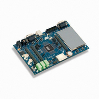
ATSAM3U-EK
Description
KIT EVAL FOR AT91SAM3U CORTEX
Manufacturer
Atmel
Type
MCUr
Datasheets
1.ATSAM3U-EK.pdf
(2 pages)
2.ATSAM3U-EK.pdf
(61 pages)
3.ATSAM3U-EK.pdf
(1171 pages)
4.ATSAM3U-EK.pdf
(53 pages)
Specifications of ATSAM3U-EK
Contents
Board
Processor To Be Evaluated
SAM3U
Data Bus Width
32 bit
Interface Type
RS-232, USB
Operating Supply Voltage
3 V
Silicon Manufacturer
Atmel
Core Architecture
ARM
Core Sub-architecture
Cortex - M3
Silicon Core Number
SAM3U4E
Silicon Family Name
SAM3U
Kit Contents
Board CD Docs
Rohs Compliant
Yes
For Use With/related Products
AT91SAM3U
Lead Free Status / RoHS Status
Lead free / RoHS Compliant
Available stocks
Company
Part Number
Manufacturer
Quantity
Price
Company:

Part Number:
ATSAM3U-EK
Manufacturer:
Atmel
Quantity:
10


36.6.4
36.6.5
36.6.6
760
760
SAM3U Series
SAM3U Series
Clock Control
TC Operating Modes
Trigger
The clock of each counter can be controlled in two different ways: it can be enabled/disabled
and started/stopped. See
•
•
Figure 36-4. Clock Control
Each channel can independently operate in two different modes:
•
•
The TC Operating Mode is programmed with the WAVE bit in the TC Channel Mode Register.
In Capture Mode, TIOA and TIOB are configured as inputs.
In Waveform Mode, TIOA is always configured to be an output and TIOB is an output if it is not
selected to be the external trigger.
A trigger resets the counter and starts the counter clock. Three types of triggers are common to
both modes, and a fourth external trigger is available to each mode.
The clock can be enabled or disabled by the user with the CLKEN and the CLKDIS
commands in the Control Register. In Capture Mode it can be disabled by an RB load event
if LDBDIS is set to 1 in TC_CMR. In Waveform Mode, it can be disabled by an RC Compare
event if CPCDIS is set to 1 in TC_CMR. When disabled, the start or the stop actions have no
effect: only a CLKEN command in the Control Register can re-enable the clock. When the
clock is enabled, the CLKSTA bit is set in the Status Register.
The clock can also be started or stopped: a trigger (software, synchro, external or compare)
always starts the clock. The clock can be stopped by an RB load event in Capture Mode
(LDBSTOP = 1 in TC_CMR) or a RC compare event in Waveform Mode (CPCSTOP = 1 in
TC_CMR). The start and the stop commands have effect only if the clock is enabled.
Capture Mode provides measurement on signals.
Waveform Mode provides wave generation.
Selected
Counter
Clock
Clock
Figure
Q
36-4.
R
S
Trigger
CLKSTA
Q
CLKEN
S
R
Event
Stop
CLKDIS
Disable
Event
6430D–ATARM–25-Mar-11
6430D–ATARM–25-Mar-11
Related parts for ATSAM3U-EK
Image
Part Number
Description
Manufacturer
Datasheet
Request
R

Part Number:
Description:
AT91 ARM Thumb-based Microcontrollers
Manufacturer:
ATMEL [ATMEL Corporation]
Datasheet:

Part Number:
Description:
DEV KIT FOR AVR/AVR32
Manufacturer:
Atmel
Datasheet:

Part Number:
Description:
INTERVAL AND WIPE/WASH WIPER CONTROL IC WITH DELAY
Manufacturer:
ATMEL Corporation
Datasheet:
Part Number:
Description:
Low-Voltage Voice-Switched IC for Hands-Free Operation
Manufacturer:
ATMEL Corporation
Datasheet:
Part Number:
Description:
MONOLITHIC INTEGRATED FEATUREPHONE CIRCUIT
Manufacturer:
ATMEL Corporation
Datasheet:
Part Number:
Description:
AM-FM Receiver IC U4255BM-M
Manufacturer:
ATMEL Corporation
Datasheet:
Part Number:
Description:
Monolithic Integrated Feature Phone Circuit
Manufacturer:
ATMEL Corporation
Datasheet:
Part Number:
Description:
Multistandard Video-IF and Quasi Parallel Sound Processing
Manufacturer:
ATMEL Corporation
Datasheet:
Part Number:
Description:
High-performance EE PLD
Manufacturer:
ATMEL Corporation
Datasheet:
Part Number:
Description:
8-bit Flash Microcontroller
Manufacturer:
ATMEL Corporation
Datasheet:
Part Number:
Description:
2-Wire Serial EEPROM
Manufacturer:
ATMEL Corporation
Datasheet: