ATSAM3U-EK Atmel, ATSAM3U-EK Datasheet - Page 717
ATSAM3U-EK
Manufacturer Part Number
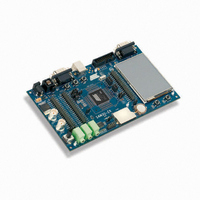
ATSAM3U-EK
Description
KIT EVAL FOR AT91SAM3U CORTEX
Manufacturer
Atmel
Type
MCUr
Datasheets
1.ATSAM3U-EK.pdf
(2 pages)
2.ATSAM3U-EK.pdf
(61 pages)
3.ATSAM3U-EK.pdf
(1171 pages)
4.ATSAM3U-EK.pdf
(53 pages)
Specifications of ATSAM3U-EK
Contents
Board
Processor To Be Evaluated
SAM3U
Data Bus Width
32 bit
Interface Type
RS-232, USB
Operating Supply Voltage
3 V
Silicon Manufacturer
Atmel
Core Architecture
ARM
Core Sub-architecture
Cortex - M3
Silicon Core Number
SAM3U4E
Silicon Family Name
SAM3U
Kit Contents
Board CD Docs
Rohs Compliant
Yes
For Use With/related Products
AT91SAM3U
Lead Free Status / RoHS Status
Lead free / RoHS Compliant
Available stocks
Company
Part Number
Manufacturer
Quantity
Price
Company:

Part Number:
ATSAM3U-EK
Manufacturer:
Atmel
Quantity:
10


35.7.5.3
Figure 35-34. IrDA Demodulator Operations
6430D–ATARM–25-Mar-11
6430D–ATARM–25-Mar-11
Receiver
Counter
Value
Input
MCK
RXD
IrDA Demodulator
6
Rejected
5
Pulse
4
Table 35-13. IrDA Baud Rate Error (Continued)
The demodulator is based on the IrDA Receive filter comprised of an 8-bit down counter which is
loaded with the value programmed in US_IF. When a falling edge is detected on the RXD pin,
the Filter Counter starts counting down at the Master Clock (MCK) speed. If a rising edge is
detected on the RXD pin, the counter stops and is reloaded with US_IF. If no rising edge is
detected when the counter reaches 0, the input of the receiver is driven low during one bit time.
Figure 35-34
As the IrDA mode uses the same logic as the ISO7816, note that the FI_DI_RATIO field in
US_FIDI must be set to a value higher than 0 in order to assure IrDA communications operate
correctly.
Peripheral Clock
3 686 400
20 000 000
32 768 000
3
2
6
illustrates the operations of the IrDA demodulator.
6
5
Baud Rate
4
Accepted
Pulse
2 400
2 400
2 400
3
2
1
0
521
853
CD
96
Baud Rate Error
0.00%
0.03%
0.04%
SAM3U Series
SAM3U Series
Pulse Time
78.13
78.13
78.13
717
717
Related parts for ATSAM3U-EK
Image
Part Number
Description
Manufacturer
Datasheet
Request
R

Part Number:
Description:
AT91 ARM Thumb-based Microcontrollers
Manufacturer:
ATMEL [ATMEL Corporation]
Datasheet:

Part Number:
Description:
DEV KIT FOR AVR/AVR32
Manufacturer:
Atmel
Datasheet:

Part Number:
Description:
INTERVAL AND WIPE/WASH WIPER CONTROL IC WITH DELAY
Manufacturer:
ATMEL Corporation
Datasheet:
Part Number:
Description:
Low-Voltage Voice-Switched IC for Hands-Free Operation
Manufacturer:
ATMEL Corporation
Datasheet:
Part Number:
Description:
MONOLITHIC INTEGRATED FEATUREPHONE CIRCUIT
Manufacturer:
ATMEL Corporation
Datasheet:
Part Number:
Description:
AM-FM Receiver IC U4255BM-M
Manufacturer:
ATMEL Corporation
Datasheet:
Part Number:
Description:
Monolithic Integrated Feature Phone Circuit
Manufacturer:
ATMEL Corporation
Datasheet:
Part Number:
Description:
Multistandard Video-IF and Quasi Parallel Sound Processing
Manufacturer:
ATMEL Corporation
Datasheet:
Part Number:
Description:
High-performance EE PLD
Manufacturer:
ATMEL Corporation
Datasheet:
Part Number:
Description:
8-bit Flash Microcontroller
Manufacturer:
ATMEL Corporation
Datasheet:
Part Number:
Description:
2-Wire Serial EEPROM
Manufacturer:
ATMEL Corporation
Datasheet: