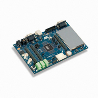
ATSAM3U-EK Atmel, ATSAM3U-EK Datasheet - Page 870

ATSAM3U-EK
Manufacturer Part Number
ATSAM3U-EK
Description
KIT EVAL FOR AT91SAM3U CORTEX
Manufacturer
Atmel
Type
MCUr
Datasheets
1.ATSAM3U-EK.pdf
(2 pages)
2.ATSAM3U-EK.pdf
(61 pages)
3.ATSAM3U-EK.pdf
(1171 pages)
4.ATSAM3U-EK.pdf
(53 pages)
Specifications of ATSAM3U-EK
Contents
Board
Processor To Be Evaluated
SAM3U
Data Bus Width
32 bit
Interface Type
RS-232, USB
Operating Supply Voltage
3 V
Silicon Manufacturer
Atmel
Core Architecture
ARM
Core Sub-architecture
Cortex - M3
Silicon Core Number
SAM3U4E
Silicon Family Name
SAM3U
Kit Contents
Board CD Docs
Rohs Compliant
Yes
For Use With/related Products
AT91SAM3U
Lead Free Status / RoHS Status
Lead free / RoHS Compliant
Available stocks
Company
Part Number
Manufacturer
Quantity
Price
Company:
Part Number:
ATSAM3U-EK
Manufacturer:
Atmel
Quantity:
10
- ATSAM3U-EK PDF datasheet
- ATSAM3U-EK PDF datasheet #2
- ATSAM3U-EK PDF datasheet #3
- ATSAM3U-EK PDF datasheet #4
- Current page: 870 of 1171
- Download datasheet (25Mb)
870
870
SAM3U Series
SAM3U Series
Figure 38-4. Non Overlapped Center Aligned Waveforms
Note:
When center aligned, the channel counter increases up to CPRD and decreases down to 0. This
ends the period.
When left aligned, the channel counter increases up to CPRD and is reset. This ends the period.
Thus, for the same CPRD value, the period for a center aligned channel is twice the period for a
left aligned channel.
Waveforms are fixed at 0 when:
Waveforms are fixed at 1 (once the channel is enabled) when:
The waveform polarity must be set before enabling the channel. This immediately affects the
channel output level. Changes on channel polarity are not taken into account while the channel
is enabled.
Besides generating output signals OCx, the comparator generates interrupts in function of the
counter value. When the output waveform is left aligned, the interrupt occurs at the end of the
counter period. When the output waveform is center aligned, the bit CES of the PWM_CMRx
register defines when the channel counter interrupt occurs. If CES is set to 0, the interrupt
occurs at the end of the counter period. If CES is set to 1, the interrupt occurs at the end of the
counter period and at half of the counter period.
Figure 38-5 “Waveform Properties”
configuration.
• the waveform polarity. At the beginning of the period, the signal can be at high or low level.
• the waveform alignment. The output waveform can be left or center aligned. Center aligned
• CDTY = CPRD and CPOL = 0
• CDTY = 0 and CPOL = 1
• CDTY = 0 and CPOL = 0
• CDTY = CPRD and CPOL = 1
This property is defined in the CPOL field of the PWM_CMRx register. By default the signal
starts by a low level.
waveforms can be used to generate non overlapped waveforms. This property is defined in
the CALG field of the PWM_CMRx register. The default mode is left aligned.
OC0
OC1
1. See
Figure 38-5 on page 871
No overlap
Period
for a detailed description of center aligned waveforms.
illustrates the counter interrupts in function of the
6430D–ATARM–25-Mar-11
6430D–ATARM–25-Mar-11
Related parts for ATSAM3U-EK
Image
Part Number
Description
Manufacturer
Datasheet
Request
R

Part Number:
Description:
AT91 ARM Thumb-based Microcontrollers
Manufacturer:
ATMEL [ATMEL Corporation]
Datasheet:

Part Number:
Description:
DEV KIT FOR AVR/AVR32
Manufacturer:
Atmel
Datasheet:

Part Number:
Description:
INTERVAL AND WIPE/WASH WIPER CONTROL IC WITH DELAY
Manufacturer:
ATMEL Corporation
Datasheet:

Part Number:
Description:
Low-Voltage Voice-Switched IC for Hands-Free Operation
Manufacturer:
ATMEL Corporation
Datasheet:

Part Number:
Description:
MONOLITHIC INTEGRATED FEATUREPHONE CIRCUIT
Manufacturer:
ATMEL Corporation
Datasheet:

Part Number:
Description:
AM-FM Receiver IC U4255BM-M
Manufacturer:
ATMEL Corporation
Datasheet:

Part Number:
Description:
Monolithic Integrated Feature Phone Circuit
Manufacturer:
ATMEL Corporation
Datasheet:

Part Number:
Description:
Multistandard Video-IF and Quasi Parallel Sound Processing
Manufacturer:
ATMEL Corporation
Datasheet:

Part Number:
Description:
High-performance EE PLD
Manufacturer:
ATMEL Corporation
Datasheet:

Part Number:
Description:
8-bit Flash Microcontroller
Manufacturer:
ATMEL Corporation
Datasheet:

Part Number:
Description:
2-Wire Serial EEPROM
Manufacturer:
ATMEL Corporation
Datasheet:


