ATSAM3U-EK Atmel, ATSAM3U-EK Datasheet - Page 888
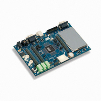
ATSAM3U-EK
Manufacturer Part Number
ATSAM3U-EK
Description
KIT EVAL FOR AT91SAM3U CORTEX
Manufacturer
Atmel
Type
MCUr
Datasheets
1.ATSAM3U-EK.pdf
(2 pages)
2.ATSAM3U-EK.pdf
(61 pages)
3.ATSAM3U-EK.pdf
(1171 pages)
4.ATSAM3U-EK.pdf
(53 pages)
Specifications of ATSAM3U-EK
Contents
Board
Processor To Be Evaluated
SAM3U
Data Bus Width
32 bit
Interface Type
RS-232, USB
Operating Supply Voltage
3 V
Silicon Manufacturer
Atmel
Core Architecture
ARM
Core Sub-architecture
Cortex - M3
Silicon Core Number
SAM3U4E
Silicon Family Name
SAM3U
Kit Contents
Board CD Docs
Rohs Compliant
Yes
For Use With/related Products
AT91SAM3U
Lead Free Status / RoHS Status
Lead free / RoHS Compliant
Available stocks
Company
Part Number
Manufacturer
Quantity
Price
Company:

Part Number:
ATSAM3U-EK
Manufacturer:
Atmel
Quantity:
10


38.6.5.2
38.6.5.3
888
888
SAM3U Series
SAM3U Series
Source Clock Selection Criteria
Changing the Duty-Cycle, the Period and the Dead-Times
The large number of source clocks can make selection difficult. The relationship between the
value in the
Cycle Register”
Period Register gives the PWM accuracy. The Duty-Cycle quantum cannot be lower than
1/CPRDx value. The higher the value of PWM_CPRDx, the greater the PWM accuracy.
For example, if the user sets 15 (in decimal) in PWM_CPRDx, the user is able to set a value
from between 1 up to 14 in PWM_CDTYx Register. The resulting duty-cycle quantum cannot be
lower than 1/15 of the PWM period.
It is possible to modulate the output waveform duty-cycle, period and dead-times.
To prevent unexpected output waveform, the user must use the
Update
Time Update Register”
waveform parameters while the channel is still enabled.
Note:
• If the channel is an asynchronous channel (SYNCx = 0 in
• If the channel is a synchronous channel and update method 0 is selected (SYNCx = 1 and
• If the channel is a synchronous channel and update method 1 or 2 is selected (SYNCx=1 and
Register”
values until the end of the current PWM period and update the values for the next period.
UPDM = 0 in PWM_SCM register), these registers hold the new period, duty-cycle and dead-
times values until the bit UPDULOCK is written at “1” (in
Control Register”
values for the next period.
UPDM=1 or 2 in PWM_SCM register):
– registers PWM_CPRDUPDx and PWM_DTUPDx hold the new period and dead-
– register PWM_CDTYUPDx holds the new duty-cycle value until the end of the
times values until the bit UPDULOCK is written at “1” (in PWM_SCUC register) and
the end of the current PWM period, then update the values for the next period.
update period of synchronous channels (when UPRCNT is equal to UPR in
Sync Channels Update Period Register”
PWM period, then updates the value for the next period.
Register”, the
If the update registers PWM_CDTYUPDx, PWM_CPRDUPDx and PWM_DTUPDx are written
several times between two updates, only the last written value is taken into account.
(PWM_SCM)), these registers hold the new period, duty-cycle and dead-times
“PWM Channel Period Register”
(PWM_CDTYx) can help the user in choosing. The event number written in the
(PWM_SCUC)) and the end of the current PWM period, then update the
“PWM Channel Period Update Register”
(PWM_CDTYUPDx, PWM_CPRDUPDx and PWM_DTUPDx) to change
(PWM_CPRDx) and the
(PWM_SCUP)) and the end of the current
“PWM Sync Channels Update
“PWM Sync Channels Mode
and the
“PWM Channel Duty Cycle
“PWM Channel Dead
“PWM Channel Duty
6430D–ATARM–25-Mar-11
6430D–ATARM–25-Mar-11
“PWM
Related parts for ATSAM3U-EK
Image
Part Number
Description
Manufacturer
Datasheet
Request
R

Part Number:
Description:
AT91 ARM Thumb-based Microcontrollers
Manufacturer:
ATMEL [ATMEL Corporation]
Datasheet:

Part Number:
Description:
DEV KIT FOR AVR/AVR32
Manufacturer:
Atmel
Datasheet:

Part Number:
Description:
INTERVAL AND WIPE/WASH WIPER CONTROL IC WITH DELAY
Manufacturer:
ATMEL Corporation
Datasheet:
Part Number:
Description:
Low-Voltage Voice-Switched IC for Hands-Free Operation
Manufacturer:
ATMEL Corporation
Datasheet:
Part Number:
Description:
MONOLITHIC INTEGRATED FEATUREPHONE CIRCUIT
Manufacturer:
ATMEL Corporation
Datasheet:
Part Number:
Description:
AM-FM Receiver IC U4255BM-M
Manufacturer:
ATMEL Corporation
Datasheet:
Part Number:
Description:
Monolithic Integrated Feature Phone Circuit
Manufacturer:
ATMEL Corporation
Datasheet:
Part Number:
Description:
Multistandard Video-IF and Quasi Parallel Sound Processing
Manufacturer:
ATMEL Corporation
Datasheet:
Part Number:
Description:
High-performance EE PLD
Manufacturer:
ATMEL Corporation
Datasheet:
Part Number:
Description:
8-bit Flash Microcontroller
Manufacturer:
ATMEL Corporation
Datasheet:
Part Number:
Description:
2-Wire Serial EEPROM
Manufacturer:
ATMEL Corporation
Datasheet: