ATSAM3U-EK Atmel, ATSAM3U-EK Datasheet - Page 1102
ATSAM3U-EK
Manufacturer Part Number
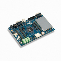
ATSAM3U-EK
Description
KIT EVAL FOR AT91SAM3U CORTEX
Manufacturer
Atmel
Type
MCUr
Datasheets
1.ATSAM3U-EK.pdf
(2 pages)
2.ATSAM3U-EK.pdf
(61 pages)
3.ATSAM3U-EK.pdf
(1171 pages)
4.ATSAM3U-EK.pdf
(53 pages)
Specifications of ATSAM3U-EK
Contents
Board
Processor To Be Evaluated
SAM3U
Data Bus Width
32 bit
Interface Type
RS-232, USB
Operating Supply Voltage
3 V
Silicon Manufacturer
Atmel
Core Architecture
ARM
Core Sub-architecture
Cortex - M3
Silicon Core Number
SAM3U4E
Silicon Family Name
SAM3U
Kit Contents
Board CD Docs
Rohs Compliant
Yes
For Use With/related Products
AT91SAM3U
Lead Free Status / RoHS Status
Lead free / RoHS Compliant
Available stocks
Company
Part Number
Manufacturer
Quantity
Price
Company:

Part Number:
ATSAM3U-EK
Manufacturer:
Atmel
Quantity:
10


Table 43-3.
Notes:
1102
Symbol
V
V
V
I
I
D
V
V
V
V
I
CD
CD
T
T
LOAD
LOAD-START
Q
ON
ON
VDDIN
VDDOUT
ACCURACY
LINE
LINE-TR
LOAD
LOAD-TR
DROPOUT
IN
OUT
1. A 10 μF or higher ceramic capacitor must be connected between VDDIN and the closest GND pin of the device.
2. To ensure stability, an external 4.7μF output capacitor, CD
3. Defined as the current needed to charge external bypass/decoupling capacitor network.
SAM3U Series
This large decoupling capacitor is mandatory to reduce startup current, improving transient response and noise rejection.
GND pin of the device. The ESR (Equivalent Series Resistance) of the capacitor must be in the range 0.5 to 10 Ohms.
Solid tantalum, and multilayer ceramic capacitors are all suitable as output capacitor.
A 100 nF bypass capacitor between VDDOUT and the closest GND pin of the device decreases output noise and improves
the load transient response.
Parameter
DC Input Voltage Range
DC Output Voltage
Output Voltage Accuracy
Maximum DC Output
Current
Maximum Peak Current
during startup
Dropout Voltage
Line Regulation
Transient Line regulation
Load Regulation
Transient Load Regulation
Quiescent Current
Input Decoupling Capacitor Cf. External Capacitor Requirements
Output Decoupling
Capacitor
Turn on Time
Turn on Time
1.8V Voltage Regulator Characteristics
(3)
Conditions
Normal Mode
Standby Mode
I
V
V
See Note
V
V
I
V
tr = tf = 5μs; I
CD
V
I
V
I
tr = tf = 5 μs
CD
Normal Mode;
@ I
@ I
Standby Mode;
Cf. External Capacitor Requirements
ESR
CD
(core power brownout detector supply rising
threshold)
CD
Load
Load
Load
Load
VDDIN
VDDIN
VDDIN
VDDIN
VDDIN
VDDIN
VDDIN
OUT
OUT
OUT
OUT
Load
Load
MAX
= 10% to 90% MAX
= 10% to 90% MAX
= 0.5mA to 150 mA
= 4.7μF, V
= 4.7μF, V
> 2.2V
≤ 2.2V
= 1.8V, I
from 2.7V to 3.6V;
≥ 2.2V;
≥ 2.2V;
from 2.7V to 3.6V;
= 4.7μF
= 4.7 μF
= 0 mA
= 150 mA
(3)
.
Load
Load
Max
VDDOUT
VDDOUT
= 60 mA
reaches 1.8V (+/- 3%)
reaches V
OUT
must be connected between the VDDOUT and the closest
TH+
(1)
(2)
Min
1.8
0.5
-3
Typ
700
120
200
1.8
4.7
3.3
20
50
20
50
10
0
7
6430D–ATARM–25-Mar-11
1200
Max
150
300
150
100
100
250
400
3.6
60
50
50
10
10
3
1
Units
Ohm
mA
mA
mV
mV
mV
μA
μF
μF
μs
μs
%
V
V
Related parts for ATSAM3U-EK
Image
Part Number
Description
Manufacturer
Datasheet
Request
R

Part Number:
Description:
AT91 ARM Thumb-based Microcontrollers
Manufacturer:
ATMEL [ATMEL Corporation]
Datasheet:

Part Number:
Description:
DEV KIT FOR AVR/AVR32
Manufacturer:
Atmel
Datasheet:

Part Number:
Description:
INTERVAL AND WIPE/WASH WIPER CONTROL IC WITH DELAY
Manufacturer:
ATMEL Corporation
Datasheet:
Part Number:
Description:
Low-Voltage Voice-Switched IC for Hands-Free Operation
Manufacturer:
ATMEL Corporation
Datasheet:
Part Number:
Description:
MONOLITHIC INTEGRATED FEATUREPHONE CIRCUIT
Manufacturer:
ATMEL Corporation
Datasheet:
Part Number:
Description:
AM-FM Receiver IC U4255BM-M
Manufacturer:
ATMEL Corporation
Datasheet:
Part Number:
Description:
Monolithic Integrated Feature Phone Circuit
Manufacturer:
ATMEL Corporation
Datasheet:
Part Number:
Description:
Multistandard Video-IF and Quasi Parallel Sound Processing
Manufacturer:
ATMEL Corporation
Datasheet:
Part Number:
Description:
High-performance EE PLD
Manufacturer:
ATMEL Corporation
Datasheet:
Part Number:
Description:
8-bit Flash Microcontroller
Manufacturer:
ATMEL Corporation
Datasheet:
Part Number:
Description:
2-Wire Serial EEPROM
Manufacturer:
ATMEL Corporation
Datasheet: