ATSAM3U-EK Atmel, ATSAM3U-EK Datasheet - Page 367
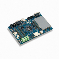
ATSAM3U-EK
Manufacturer Part Number
ATSAM3U-EK
Description
KIT EVAL FOR AT91SAM3U CORTEX
Manufacturer
Atmel
Type
MCUr
Datasheets
1.ATSAM3U-EK.pdf
(2 pages)
2.ATSAM3U-EK.pdf
(61 pages)
3.ATSAM3U-EK.pdf
(1171 pages)
4.ATSAM3U-EK.pdf
(53 pages)
Specifications of ATSAM3U-EK
Contents
Board
Processor To Be Evaluated
SAM3U
Data Bus Width
32 bit
Interface Type
RS-232, USB
Operating Supply Voltage
3 V
Silicon Manufacturer
Atmel
Core Architecture
ARM
Core Sub-architecture
Cortex - M3
Silicon Core Number
SAM3U4E
Silicon Family Name
SAM3U
Kit Contents
Board CD Docs
Rohs Compliant
Yes
For Use With/related Products
AT91SAM3U
Lead Free Status / RoHS Status
Lead free / RoHS Compliant
Available stocks
Company
Part Number
Manufacturer
Quantity
Price
Company:

Part Number:
ATSAM3U-EK
Manufacturer:
Atmel
Quantity:
10


25.12 Automatic Wait States
25.12.1
Figure 25-13. Chip Select Wait State between a Read Access on NCS0 and a Write Access on NCS2
6430D–ATARM–25-Mar-11
6430D–ATARM–25-Mar-11
Chip Select Wait States
NBS0, NBS1,
D[15:0]
A[23:2]
A0,A1
NCS0
NCS2
NWE
MCK
NRD
One bit is dedicated to enable/disable NAND Flash scrambling and one bit is dedicated
enable/disable scrambling the off chip SRAM. When at least one external SRAM is scrambled,
the SMSC field must be set in the SMC_OCMS register.
When multiple chip selects (external SRAM) are handled, it is possible to configure the scram-
bling function per chip select using the OCMS field in the SMC_TIMINGS registers.
To scramble the NAND Flash contents, the SRSE field must be set in the SMC_OCMS register.
When NAND Flash memory content is scrambled, the on-chip SRAM page buffer associated for
the transfer is also scrambled.
Under certain circumstances, the SMC automatically inserts idle cycles between accesses to
avoid bus contention or operation conflict.
The SMC always inserts an idle cycle between 2 transfers on separate chip selects. This idle
cycle ensures that there is no bus contention between the de-activation of one device and the
activation of the next one.
During chip select wait state, all control lines are turned inactive: NBS0 to NBS1, NWR0 to
NWR1, NCS[0..3], and NRD lines. They are all set to 1.
Figure 25-13
Select 2.
NRD_CYCLE
illustrates a chip select wait state between access on Chip Select 0 and Chip
Read to Write
Wait State
Chip Select
Wait State
NWE_CYCLE
SAM3U Series
SAM3U Series
367
367
Related parts for ATSAM3U-EK
Image
Part Number
Description
Manufacturer
Datasheet
Request
R

Part Number:
Description:
AT91 ARM Thumb-based Microcontrollers
Manufacturer:
ATMEL [ATMEL Corporation]
Datasheet:

Part Number:
Description:
DEV KIT FOR AVR/AVR32
Manufacturer:
Atmel
Datasheet:

Part Number:
Description:
INTERVAL AND WIPE/WASH WIPER CONTROL IC WITH DELAY
Manufacturer:
ATMEL Corporation
Datasheet:
Part Number:
Description:
Low-Voltage Voice-Switched IC for Hands-Free Operation
Manufacturer:
ATMEL Corporation
Datasheet:
Part Number:
Description:
MONOLITHIC INTEGRATED FEATUREPHONE CIRCUIT
Manufacturer:
ATMEL Corporation
Datasheet:
Part Number:
Description:
AM-FM Receiver IC U4255BM-M
Manufacturer:
ATMEL Corporation
Datasheet:
Part Number:
Description:
Monolithic Integrated Feature Phone Circuit
Manufacturer:
ATMEL Corporation
Datasheet:
Part Number:
Description:
Multistandard Video-IF and Quasi Parallel Sound Processing
Manufacturer:
ATMEL Corporation
Datasheet:
Part Number:
Description:
High-performance EE PLD
Manufacturer:
ATMEL Corporation
Datasheet:
Part Number:
Description:
8-bit Flash Microcontroller
Manufacturer:
ATMEL Corporation
Datasheet:
Part Number:
Description:
2-Wire Serial EEPROM
Manufacturer:
ATMEL Corporation
Datasheet: