ATSAM3U-EK Atmel, ATSAM3U-EK Datasheet - Page 718
ATSAM3U-EK
Manufacturer Part Number
ATSAM3U-EK
Description
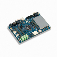
KIT EVAL FOR AT91SAM3U CORTEX
Manufacturer
Atmel
Type
MCUr
Datasheets
1.ATSAM3U-EK.pdf
(2 pages)
2.ATSAM3U-EK.pdf
(61 pages)
3.ATSAM3U-EK.pdf
(1171 pages)
4.ATSAM3U-EK.pdf
(53 pages)
Specifications of ATSAM3U-EK
Contents
Board
Processor To Be Evaluated
SAM3U
Data Bus Width
32 bit
Interface Type
RS-232, USB
Operating Supply Voltage
3 V
Silicon Manufacturer
Atmel
Core Architecture
ARM
Core Sub-architecture
Cortex - M3
Silicon Core Number
SAM3U4E
Silicon Family Name
SAM3U
Kit Contents
Board CD Docs
Rohs Compliant
Yes
For Use With/related Products
AT91SAM3U
Lead Free Status / RoHS Status
Lead free / RoHS Compliant
Available stocks
Company
Part Number
Manufacturer
Quantity
Price
Company:

Part Number:
ATSAM3U-EK
Manufacturer:
Atmel
Quantity:
10


35.7.6
718
718
SAM3U Series
SAM3U Series
RS485 Mode
The USART features the RS485 mode to enable line driver control. While operating in RS485
mode, the USART behaves as though in asynchronous or synchronous mode and configuration
of all the parameters is possible. The difference is that the RTS pin is driven high when the
transmitter is operating. The behavior of the RTS pin is controlled by the TXEMPTY bit. A typical
connection of the USART to a RS485 bus is shown in
Figure 35-35. Typical Connection to a RS485 Bus
The USART is set in RS485 mode by programming the USART_MODE field in the Mode Regis-
ter (US_MR) to the value 0x1.
The RTS pin is at a level inverse to the TXEMPTY bit. Significantly, the RTS pin remains high
when a timeguard is programmed so that the line can remain driven after the last character com-
pletion.
when the timeguard is enabled.
Figure 35-36. Example of RTS Drive with Timeguard
Figure 35-36
Baud Rate
TXEMPTY
US_THR
TXRDY
Clock
Write
TXD
RTS
gives an example of the RTS waveform during a character transmission
USART
Start
Bit
D0
RXD
TXD
RTS
D1
D2
D3
D4
D5
D6
Figure
D7
Parity
Bit
35-35.
Stop
Bit
Differential
Bus
TG = 4
6430D–ATARM–25-Mar-11
6430D–ATARM–25-Mar-11
Related parts for ATSAM3U-EK
Image
Part Number
Description
Manufacturer
Datasheet
Request
R

Part Number:
Description:
AT91 ARM Thumb-based Microcontrollers
Manufacturer:
ATMEL [ATMEL Corporation]
Datasheet:

Part Number:
Description:
DEV KIT FOR AVR/AVR32
Manufacturer:
Atmel
Datasheet:

Part Number:
Description:
INTERVAL AND WIPE/WASH WIPER CONTROL IC WITH DELAY
Manufacturer:
ATMEL Corporation
Datasheet:
Part Number:
Description:
Low-Voltage Voice-Switched IC for Hands-Free Operation
Manufacturer:
ATMEL Corporation
Datasheet:
Part Number:
Description:
MONOLITHIC INTEGRATED FEATUREPHONE CIRCUIT
Manufacturer:
ATMEL Corporation
Datasheet:
Part Number:
Description:
AM-FM Receiver IC U4255BM-M
Manufacturer:
ATMEL Corporation
Datasheet:
Part Number:
Description:
Monolithic Integrated Feature Phone Circuit
Manufacturer:
ATMEL Corporation
Datasheet:
Part Number:
Description:
Multistandard Video-IF and Quasi Parallel Sound Processing
Manufacturer:
ATMEL Corporation
Datasheet:
Part Number:
Description:
High-performance EE PLD
Manufacturer:
ATMEL Corporation
Datasheet:
Part Number:
Description:
8-bit Flash Microcontroller
Manufacturer:
ATMEL Corporation
Datasheet:
Part Number:
Description:
2-Wire Serial EEPROM
Manufacturer:
ATMEL Corporation
Datasheet: