ATSAM3U-EK Atmel, ATSAM3U-EK Datasheet - Page 457
ATSAM3U-EK
Manufacturer Part Number
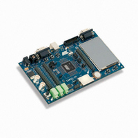
ATSAM3U-EK
Description
KIT EVAL FOR AT91SAM3U CORTEX
Manufacturer
Atmel
Type
MCUr
Datasheets
1.ATSAM3U-EK.pdf
(2 pages)
2.ATSAM3U-EK.pdf
(61 pages)
3.ATSAM3U-EK.pdf
(1171 pages)
4.ATSAM3U-EK.pdf
(53 pages)
Specifications of ATSAM3U-EK
Contents
Board
Processor To Be Evaluated
SAM3U
Data Bus Width
32 bit
Interface Type
RS-232, USB
Operating Supply Voltage
3 V
Silicon Manufacturer
Atmel
Core Architecture
ARM
Core Sub-architecture
Cortex - M3
Silicon Core Number
SAM3U4E
Silicon Family Name
SAM3U
Kit Contents
Board CD Docs
Rohs Compliant
Yes
For Use With/related Products
AT91SAM3U
Lead Free Status / RoHS Status
Lead free / RoHS Compliant
Available stocks
Company
Part Number
Manufacturer
Quantity
Price
Company:

Part Number:
ATSAM3U-EK
Manufacturer:
Atmel
Quantity:
10


27.4.2
27.4.3
6430D–ATARM–25-Mar-11
3 to 20 MHz Crystal Oscillator
Main Clock Oscillator Selection
this frequency selection, the MOSCRCS bit in the Power Management Controller Status Regis-
ter (PMC_SR) is automatically cleared and MAINCK is stopped until the oscillator is stabilized.
Once the oscillator is stabilized, MAINCK restarts and MOSCRCS is set.
When disabling the Main Clock by clearing the MOSCRCEN bit in CKGR_MOR, the MOSCRCS
bit in the Power Management Controller Status Register (PMC_SR) is automatically cleared,
indicating the Main Clock is off.
Setting the MOSCRCS bit in the Power Management Controller Interrupt Enable Register
(PMC_IER) can trigger an interrupt to the processor.
After reset, the 3 to 20 MHz Crystal Oscillator is disabled and it is not selected as the source of
MAINCK.
The user can select the 3 to 20 MHz crystal oscillator to be the source of MAINCK, as it provides
a more accurate frequency. The software enables or disables the main oscillator so as to reduce
power consumption by clearing the MOSCXTEN bit in the Main Oscillator Register
(CKGR_MOR).
When disabling the main oscillator by clearing the MOSCXTEN bit in CKGR_MOR, the
MOSCXTS bit in PMC_SR is automatically cleared, indicating the Main Clock is off.
When enabling the main oscillator, the user must initiate the main oscillator counter with a value
corresponding to the startup time of the oscillator. This startup time depends on the crystal fre-
quency connected to the oscillator.
When the MOSCXTEN bit and the MOSCXTCNT are written in CKGR_MOR to enable the main
oscillator, the MOSCXTS bit in the Power Management Controller Status Register (PMC_SR) is
cleared and the counter starts counting down on the slow clock divided by 8 from the MOSCX-
TCNT value. Since the MOSCXTCNT value is coded with 8 bits, the maximum startup time is
about 62 ms.
When the counter reaches 0, the MOSCXTS bit is set, indicating that the main clock is valid.
Setting the MOSCXTS bit in PMC_IMR can trigger an interrupt to the processor.
The user can select either the 4/8/12 MHz Fast RC Oscillator or the 3 to 20 MHz Crystal Oscilla-
tor to be the source of Main Clock.
The advantage of the 4/8/12 MHz Fast RC Oscillator is to have fast startup time, this is why it is
selected by default (to start up the system) and when entering in Wait Mode.
The advantage of the 3 to 20 MHz Crystal Oscillator is that it is very accurate.
The selection is made by writing the MOSCSEL bit in the Main Oscillator Register
(CKGR_MOR). The switch of the Main Clock source is glitch free, so there is no need to run out
of SLCK, PLLACK or UPLLCK in order to change the selection. The MOSCSELS bit of the
Power Management Controller Status Register (PMC_SR) allows knowing when the switch
sequence is done.
Setting the MOSCSELS bit in PMC_IMR can trigger an interrupt to the processor.
SAM3U Series
457
Related parts for ATSAM3U-EK
Image
Part Number
Description
Manufacturer
Datasheet
Request
R

Part Number:
Description:
AT91 ARM Thumb-based Microcontrollers
Manufacturer:
ATMEL [ATMEL Corporation]
Datasheet:

Part Number:
Description:
DEV KIT FOR AVR/AVR32
Manufacturer:
Atmel
Datasheet:

Part Number:
Description:
INTERVAL AND WIPE/WASH WIPER CONTROL IC WITH DELAY
Manufacturer:
ATMEL Corporation
Datasheet:
Part Number:
Description:
Low-Voltage Voice-Switched IC for Hands-Free Operation
Manufacturer:
ATMEL Corporation
Datasheet:
Part Number:
Description:
MONOLITHIC INTEGRATED FEATUREPHONE CIRCUIT
Manufacturer:
ATMEL Corporation
Datasheet:
Part Number:
Description:
AM-FM Receiver IC U4255BM-M
Manufacturer:
ATMEL Corporation
Datasheet:
Part Number:
Description:
Monolithic Integrated Feature Phone Circuit
Manufacturer:
ATMEL Corporation
Datasheet:
Part Number:
Description:
Multistandard Video-IF and Quasi Parallel Sound Processing
Manufacturer:
ATMEL Corporation
Datasheet:
Part Number:
Description:
High-performance EE PLD
Manufacturer:
ATMEL Corporation
Datasheet:
Part Number:
Description:
8-bit Flash Microcontroller
Manufacturer:
ATMEL Corporation
Datasheet:
Part Number:
Description:
2-Wire Serial EEPROM
Manufacturer:
ATMEL Corporation
Datasheet: