ATSAM3U-EK Atmel, ATSAM3U-EK Datasheet - Page 1081
ATSAM3U-EK
Manufacturer Part Number
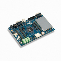
ATSAM3U-EK
Description
KIT EVAL FOR AT91SAM3U CORTEX
Manufacturer
Atmel
Type
MCUr
Datasheets
1.ATSAM3U-EK.pdf
(2 pages)
2.ATSAM3U-EK.pdf
(61 pages)
3.ATSAM3U-EK.pdf
(1171 pages)
4.ATSAM3U-EK.pdf
(53 pages)
Specifications of ATSAM3U-EK
Contents
Board
Processor To Be Evaluated
SAM3U
Data Bus Width
32 bit
Interface Type
RS-232, USB
Operating Supply Voltage
3 V
Silicon Manufacturer
Atmel
Core Architecture
ARM
Core Sub-architecture
Cortex - M3
Silicon Core Number
SAM3U4E
Silicon Family Name
SAM3U
Kit Contents
Board CD Docs
Rohs Compliant
Yes
For Use With/related Products
AT91SAM3U
Lead Free Status / RoHS Status
Lead free / RoHS Compliant
Available stocks
Company
Part Number
Manufacturer
Quantity
Price
Company:

Part Number:
ATSAM3U-EK
Manufacturer:
Atmel
Quantity:
10


42.5
42.5.1
42.5.2
42.5.3
6430D–ATARM–25-Mar-11
Functional Description
Analog-to-digital Conversion
Conversion Reference
Conversion Resolution
The ADC uses the ADC Clock to perform conversions. Converting a single analog value to a 10-
bit digital data requires Sample and Hold Clock cycles as defined in the field SHTIM of the
Mode Register” on page 1088
in the PRESCAL field of the Mode Register (ADC_MR).
The ADC clock range is between MCK/2, if PRESCAL is 0, and MCK/128, if PRESCAL is set to
63 (0x3F). PRESCAL must be programmed in order to provide an ADC clock frequency accord-
ing to the parameters given in the Product definition section.
The conversion is performed on a full range between 0V and the reference voltage pin ADVREF
Analog inputs between these voltages convert to values based on a linear conversion.
The ADC supports 8-bit or 10-bit resolutions. The 8-bit selection is performed by setting the bit
LOWRES in the ADC Mode Register (ADC_MR). By default, after a reset, the resolution is the
highest and the DATA field in the data registers is fully used. By setting the bit LOWRES, the
ADC switches in the lowest resolution and the conversion results can be read in the eight lowest
significant bits of the data registers. The two highest bits of the DATA field in the corresponding
ADC_CDR register and of the LDATA field in the ADC_LCDR register read 0.
Moreover, when a PDC channel is connected to the ADC, 10-bit resolution sets the transfer
request sizes to 16-bit. Setting the bit LOWRES automatically switches to 8-bit data transfers. In
this case, the destination buffers are optimized.
and 10 ADC Clock cycles. The ADC Clock frequency is selected
SAM3U Series
“ADC
1081
Related parts for ATSAM3U-EK
Image
Part Number
Description
Manufacturer
Datasheet
Request
R

Part Number:
Description:
AT91 ARM Thumb-based Microcontrollers
Manufacturer:
ATMEL [ATMEL Corporation]
Datasheet:

Part Number:
Description:
DEV KIT FOR AVR/AVR32
Manufacturer:
Atmel
Datasheet:

Part Number:
Description:
INTERVAL AND WIPE/WASH WIPER CONTROL IC WITH DELAY
Manufacturer:
ATMEL Corporation
Datasheet:
Part Number:
Description:
Low-Voltage Voice-Switched IC for Hands-Free Operation
Manufacturer:
ATMEL Corporation
Datasheet:
Part Number:
Description:
MONOLITHIC INTEGRATED FEATUREPHONE CIRCUIT
Manufacturer:
ATMEL Corporation
Datasheet:
Part Number:
Description:
AM-FM Receiver IC U4255BM-M
Manufacturer:
ATMEL Corporation
Datasheet:
Part Number:
Description:
Monolithic Integrated Feature Phone Circuit
Manufacturer:
ATMEL Corporation
Datasheet:
Part Number:
Description:
Multistandard Video-IF and Quasi Parallel Sound Processing
Manufacturer:
ATMEL Corporation
Datasheet:
Part Number:
Description:
High-performance EE PLD
Manufacturer:
ATMEL Corporation
Datasheet:
Part Number:
Description:
8-bit Flash Microcontroller
Manufacturer:
ATMEL Corporation
Datasheet:
Part Number:
Description:
2-Wire Serial EEPROM
Manufacturer:
ATMEL Corporation
Datasheet: