ATSAM3U-EK Atmel, ATSAM3U-EK Datasheet - Page 236
ATSAM3U-EK
Manufacturer Part Number
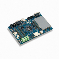
ATSAM3U-EK
Description
KIT EVAL FOR AT91SAM3U CORTEX
Manufacturer
Atmel
Type
MCUr
Datasheets
1.ATSAM3U-EK.pdf
(2 pages)
2.ATSAM3U-EK.pdf
(61 pages)
3.ATSAM3U-EK.pdf
(1171 pages)
4.ATSAM3U-EK.pdf
(53 pages)
Specifications of ATSAM3U-EK
Contents
Board
Processor To Be Evaluated
SAM3U
Data Bus Width
32 bit
Interface Type
RS-232, USB
Operating Supply Voltage
3 V
Silicon Manufacturer
Atmel
Core Architecture
ARM
Core Sub-architecture
Cortex - M3
Silicon Core Number
SAM3U4E
Silicon Family Name
SAM3U
Kit Contents
Board CD Docs
Rohs Compliant
Yes
For Use With/related Products
AT91SAM3U
Lead Free Status / RoHS Status
Lead free / RoHS Compliant
Available stocks
Company
Part Number
Manufacturer
Quantity
Price
Company:

Part Number:
ATSAM3U-EK
Manufacturer:
Atmel
Quantity:
10


14.4.6
14.4.6.1
236
SAM3U Series
ITM (Instrumentation Trace Macrocell)
How to Configure the ITM
The DWT contains counters for the items that follow:
The ITM is an application driven trace source that supports printf style debugging to trace Oper-
ating System (OS) and application events, and emits diagnostic system information. The ITM
emits trace information as packets which can be generated by three different sources with sev-
eral priority levels:
The following example describes how to output trace data in asynchronous trace mode.
• Watchpoint event to halt core
• Clock cycle (CYCCNT)
• Folded instructions
• Load Store Unit (LSU) operations
• Sleep Cycles
• CPI (all instruction cycles except for the first cycle)
• Interrupt overhead
• Software trace: Software can write directly to ITM stimulus registers. This can be done
• Hardware trace: The ITM emits packets generated by the DWT.
• Time stamping: Timestamps are emitted relative to packets. The ITM contains a 21-bit
• Configure the TPIU for asynchronous trace mode (refer to
• Enable the write accesses into the ITM registers by writing “0xC5ACCE55” into the
• Write 0x00010015 into the Trace Control Register:
• Write 0x1 into the Trace Enable Register:
• Write 0x1 into the Trace Privilege Register:
• Write into the Stimulus port 0 register: TPIU (Trace Port Interface Unit)
thanks to the “printf” function. For more information, refer to
Configure the
counter to generate the timestamp.
Configure the
Lock Access Register (Address: 0xE0000FB0)
The TPIU acts as a bridge between the on-chip trace data and the Instruction Trace Macro-
cell (ITM).
The TPIU formats and transmits trace data off-chip at frequencies asynchronous to the core.
– Enable ITM
– Enable Synchronization packets
– Enable SWO behavior
– Fix the ATB ID to 1
– Enable the Stimulus port 0
– Stimulus port 0 only accessed in privileged mode (Clearing a bit in this register will
result in the corresponding stimulus port being accessible in user mode.)
ITM”.
TPIU”)
Section 14.4.6.3 “5.4.3. How to
Section 14.4.6.1 “How to
6430D–ATARM–25-Mar-11
Related parts for ATSAM3U-EK
Image
Part Number
Description
Manufacturer
Datasheet
Request
R

Part Number:
Description:
AT91 ARM Thumb-based Microcontrollers
Manufacturer:
ATMEL [ATMEL Corporation]
Datasheet:

Part Number:
Description:
DEV KIT FOR AVR/AVR32
Manufacturer:
Atmel
Datasheet:

Part Number:
Description:
INTERVAL AND WIPE/WASH WIPER CONTROL IC WITH DELAY
Manufacturer:
ATMEL Corporation
Datasheet:
Part Number:
Description:
Low-Voltage Voice-Switched IC for Hands-Free Operation
Manufacturer:
ATMEL Corporation
Datasheet:
Part Number:
Description:
MONOLITHIC INTEGRATED FEATUREPHONE CIRCUIT
Manufacturer:
ATMEL Corporation
Datasheet:
Part Number:
Description:
AM-FM Receiver IC U4255BM-M
Manufacturer:
ATMEL Corporation
Datasheet:
Part Number:
Description:
Monolithic Integrated Feature Phone Circuit
Manufacturer:
ATMEL Corporation
Datasheet:
Part Number:
Description:
Multistandard Video-IF and Quasi Parallel Sound Processing
Manufacturer:
ATMEL Corporation
Datasheet:
Part Number:
Description:
High-performance EE PLD
Manufacturer:
ATMEL Corporation
Datasheet:
Part Number:
Description:
8-bit Flash Microcontroller
Manufacturer:
ATMEL Corporation
Datasheet:
Part Number:
Description:
2-Wire Serial EEPROM
Manufacturer:
ATMEL Corporation
Datasheet: