ATSAM3U-EK Atmel, ATSAM3U-EK Datasheet - Page 505
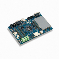
ATSAM3U-EK
Manufacturer Part Number
ATSAM3U-EK
Description
KIT EVAL FOR AT91SAM3U CORTEX
Manufacturer
Atmel
Type
MCUr
Datasheets
1.ATSAM3U-EK.pdf
(2 pages)
2.ATSAM3U-EK.pdf
(61 pages)
3.ATSAM3U-EK.pdf
(1171 pages)
4.ATSAM3U-EK.pdf
(53 pages)
Specifications of ATSAM3U-EK
Contents
Board
Processor To Be Evaluated
SAM3U
Data Bus Width
32 bit
Interface Type
RS-232, USB
Operating Supply Voltage
3 V
Silicon Manufacturer
Atmel
Core Architecture
ARM
Core Sub-architecture
Cortex - M3
Silicon Core Number
SAM3U4E
Silicon Family Name
SAM3U
Kit Contents
Board CD Docs
Rohs Compliant
Yes
For Use With/related Products
AT91SAM3U
Lead Free Status / RoHS Status
Lead free / RoHS Compliant
Available stocks
Company
Part Number
Manufacturer
Quantity
Price
Company:

Part Number:
ATSAM3U-EK
Manufacturer:
Atmel
Quantity:
10


30.4
30.4.1
30.4.2
30.4.3
6430D–ATARM–25-Mar-11
6430D–ATARM–25-Mar-11
Product Dependencies
Pin Multiplexing
Power Management
Interrupt Generation
Each pin is configurable, according to product definition as either a general-purpose I/O line
only, or as an I/O line multiplexed with one or two peripheral I/Os. As the multiplexing is hard-
ware defined and thus product-dependent, the hardware designer and programmer must
carefully determine the configuration of the PIO controllers required by their application. When
an I/O line is general-purpose only, i.e. not multiplexed with any peripheral I/O, programming of
the PIO Controller regarding the assignment to a peripheral has no effect and only the PIO Con-
troller can control how the pin is driven by the product.
The Power Management Controller controls the PIO Controller clock in order to save power.
Writing any of the registers of the user interface does not require the PIO Controller clock to be
enabled. This means that the configuration of the I/O lines does not require the PIO Controller
clock to be enabled.
However, when the clock is disabled, not all of the features of the PIO Controller are available,
including glitch filtering. Note that the Input Change Interrupt, Interrupt Modes on a programma-
ble event and the read of the pin level require the clock to be validated.
After a hardware reset, the PIO clock is disabled by default.
The user must configure the Power Management Controller before any access to the input line
information.
The PIO COntroller is connected on one of the sources of the Nested Vectored Interrupt Control-
ler (NVIC). Using the PIO Controller requires the NVIC to be programmed first.
The PIO Controller interrupt can be generated only if the PIO Controller clock is enabled.
SAM3U Series
SAM3U Series
505
505
Related parts for ATSAM3U-EK
Image
Part Number
Description
Manufacturer
Datasheet
Request
R

Part Number:
Description:
AT91 ARM Thumb-based Microcontrollers
Manufacturer:
ATMEL [ATMEL Corporation]
Datasheet:

Part Number:
Description:
DEV KIT FOR AVR/AVR32
Manufacturer:
Atmel
Datasheet:

Part Number:
Description:
INTERVAL AND WIPE/WASH WIPER CONTROL IC WITH DELAY
Manufacturer:
ATMEL Corporation
Datasheet:
Part Number:
Description:
Low-Voltage Voice-Switched IC for Hands-Free Operation
Manufacturer:
ATMEL Corporation
Datasheet:
Part Number:
Description:
MONOLITHIC INTEGRATED FEATUREPHONE CIRCUIT
Manufacturer:
ATMEL Corporation
Datasheet:
Part Number:
Description:
AM-FM Receiver IC U4255BM-M
Manufacturer:
ATMEL Corporation
Datasheet:
Part Number:
Description:
Monolithic Integrated Feature Phone Circuit
Manufacturer:
ATMEL Corporation
Datasheet:
Part Number:
Description:
Multistandard Video-IF and Quasi Parallel Sound Processing
Manufacturer:
ATMEL Corporation
Datasheet:
Part Number:
Description:
High-performance EE PLD
Manufacturer:
ATMEL Corporation
Datasheet:
Part Number:
Description:
8-bit Flash Microcontroller
Manufacturer:
ATMEL Corporation
Datasheet:
Part Number:
Description:
2-Wire Serial EEPROM
Manufacturer:
ATMEL Corporation
Datasheet: