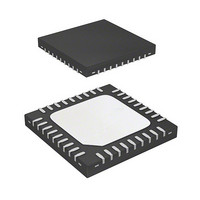
R5F213J6CNNP#U0 Renesas Electronics America, R5F213J6CNNP#U0 Datasheet - Page 20

R5F213J6CNNP#U0
Manufacturer Part Number
R5F213J6CNNP#U0
Description
MCU 1KB FLASH 32K ROM 36-QFN
Manufacturer
Renesas Electronics America
Series
R8C/3x/3JCr
Datasheet
1.R5F213J6CNNPU0.pdf
(750 pages)
Specifications of R5F213J6CNNP#U0
Core Processor
R8C
Core Size
16/32-Bit
Speed
20MHz
Connectivity
I²C, LIN, SIO, SSU, UART/USART
Peripherals
POR, PWM, Voltage Detect, WDT
Number Of I /o
31
Program Memory Size
32KB (32K x 8)
Program Memory Type
FLASH
Ram Size
2.5K x 8
Voltage - Supply (vcc/vdd)
1.8 V ~ 5.5 V
Data Converters
A/D 10x10b, D/A 2x8b
Oscillator Type
Internal
Operating Temperature
-20°C ~ 85°C
Package / Case
36-WQFN Exposed Pad, 36-HWQFN
Lead Free Status / RoHS Status
Lead free / RoHS Compliant
Eeprom Size
-
Available stocks
Company
Part Number
Manufacturer
Quantity
Price
- Current page: 20 of 750
- Download datasheet (8Mb)
24.
25.
23.5
23.6
23.7
24.1
25.1
25.2
25.3
25.4
25.5
23.4.4
23.4.5
23.4.6
23.4.7
23.5.1
23.5.2
23.5.3
23.5.4
23.5.5
23.5.6
23.5.7
23.6.1
23.6.2
23.6.3
23.7.1
23.7.2
25.2.1
25.2.2
25.2.3
25.2.4
25.2.5
25.2.6
25.2.7
25.2.8
25.2.9
25.2.10 SS Status Register (SSSR) ................................................................................................................ 501
25.2.11 SS Mode Register 2 (SSMR2) .......................................................................................................... 502
25.3.1
25.3.2
25.3.3
25.3.4
25.4.1
25.4.2
25.4.3
25.5.1
25.5.2
Clock Synchronous Serial Interface ............................................................................................ 492
Synchronous Serial Communication Unit (SSU) ........................................................................ 493
Special Mode 1 (I
Multiprocessor Communication Function ............................................................................................. 483
Notes on Serial Interface (UART2) ....................................................................................................... 490
Mode Selection ...................................................................................................................................... 492
Overview ............................................................................................................................................... 493
Registers ................................................................................................................................................ 495
Common Items for Multiple Modes ...................................................................................................... 503
Clock Synchronous Communication Mode .......................................................................................... 508
Operation in 4-Wire Bus Communication Mode .................................................................................. 515
Serial Data Logic Switching Function .............................................................................................. 471
TXD and RXD I/O Polarity Inverse Function .................................................................................. 471
CTS/RTS Function ............................................................................................................................ 472
RXD2 Digital Filter Select Function ................................................................................................ 472
Detection of Start and Stop Conditions ............................................................................................ 479
Output of Start and Stop Conditions ................................................................................................. 480
Transfer Clock .................................................................................................................................. 481
SDA Output ...................................................................................................................................... 481
SDA Input ......................................................................................................................................... 481
ACK and NACK ............................................................................................................................... 481
Initialization of Transmission/Reception .......................................................................................... 482
Multiprocessor Transmission ............................................................................................................ 486
Multiprocessor Reception ................................................................................................................. 487
RXD2 Digital Filter Select Function ................................................................................................ 489
Clock Synchronous Serial I/O Mode ................................................................................................ 490
Special Mode 1 (I
Module Standby Control Register (MSTCR) ................................................................................... 495
SSU/IIC Pin Select Register (SSUIICSR) ........................................................................................ 495
SS Bit Counter Register (SSBR) ...................................................................................................... 496
SS Transmit Data Register (SSTDR) ................................................................................................ 496
SS Receive Data Register (SSRDR) ................................................................................................. 497
SS Control Register H (SSCRH) ...................................................................................................... 497
SS Control Register L (SSCRL) ....................................................................................................... 498
SS Mode Register (SSMR) ............................................................................................................... 499
SS Enable Register (SSER) .............................................................................................................. 500
Transfer Clock .................................................................................................................................. 503
SS Shift Register (SSTRSR) ............................................................................................................. 505
Interrupt Requests ............................................................................................................................. 506
Communication Modes and Pin Functions ....................................................................................... 507
Initialization in Clock Synchronous Communication Mode ............................................................ 508
Data Transmission ............................................................................................................................ 509
Data Reception .................................................................................................................................. 511
Initialization in 4-Wire Bus Communication Mode ......................................................................... 516
Data Transmission ............................................................................................................................ 517
2
C Mode) .................................................................................................................. 473
2
C Mode) .............................................................................................................. 491
A - 13
Related parts for R5F213J6CNNP#U0
Image
Part Number
Description
Manufacturer
Datasheet
Request
R

Part Number:
Description:
KIT STARTER FOR M16C/29
Manufacturer:
Renesas Electronics America
Datasheet:

Part Number:
Description:
KIT STARTER FOR R8C/2D
Manufacturer:
Renesas Electronics America
Datasheet:

Part Number:
Description:
R0K33062P STARTER KIT
Manufacturer:
Renesas Electronics America
Datasheet:

Part Number:
Description:
KIT STARTER FOR R8C/23 E8A
Manufacturer:
Renesas Electronics America
Datasheet:

Part Number:
Description:
KIT STARTER FOR R8C/25
Manufacturer:
Renesas Electronics America
Datasheet:

Part Number:
Description:
KIT STARTER H8S2456 SHARPE DSPLY
Manufacturer:
Renesas Electronics America
Datasheet:

Part Number:
Description:
KIT STARTER FOR R8C38C
Manufacturer:
Renesas Electronics America
Datasheet:

Part Number:
Description:
KIT STARTER FOR R8C35C
Manufacturer:
Renesas Electronics America
Datasheet:

Part Number:
Description:
KIT STARTER FOR R8CL3AC+LCD APPS
Manufacturer:
Renesas Electronics America
Datasheet:

Part Number:
Description:
KIT STARTER FOR RX610
Manufacturer:
Renesas Electronics America
Datasheet:

Part Number:
Description:
KIT STARTER FOR R32C/118
Manufacturer:
Renesas Electronics America
Datasheet:

Part Number:
Description:
KIT DEV RSK-R8C/26-29
Manufacturer:
Renesas Electronics America
Datasheet:

Part Number:
Description:
KIT STARTER FOR SH7124
Manufacturer:
Renesas Electronics America
Datasheet:

Part Number:
Description:
KIT STARTER FOR H8SX/1622
Manufacturer:
Renesas Electronics America
Datasheet:

Part Number:
Description:
KIT DEV FOR SH7203
Manufacturer:
Renesas Electronics America
Datasheet:


