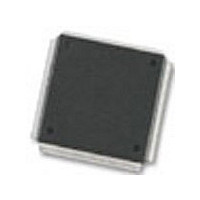
MC68376BAMFT20 Freescale Semiconductor, MC68376BAMFT20 Datasheet - Page 159

MC68376BAMFT20
Manufacturer Part Number
MC68376BAMFT20
Description
Manufacturer
Freescale Semiconductor
Datasheet
1.MC68376BAMFT20.pdf
(434 pages)
Specifications of MC68376BAMFT20
Cpu Family
68K/M683xx
Device Core
ColdFire
Device Core Size
32b
Frequency (max)
20MHz
Interface Type
QSPI/SCI
Program Memory Type
ROM
Program Memory Size
8KB
Total Internal Ram Size
7.5KB
# I/os (max)
18
Number Of Timers - General Purpose
2
Operating Supply Voltage (typ)
5V
Operating Supply Voltage (max)
5.25V
Operating Supply Voltage (min)
4.75V
On-chip Adc
16-chx10-bit
Instruction Set Architecture
RISC
Operating Temp Range
-40C to 125C
Operating Temperature Classification
Automotive
Mounting
Surface Mount
Pin Count
160
Package Type
PQFP
Lead Free Status / Rohs Status
Not Compliant
Available stocks
Company
Part Number
Manufacturer
Quantity
Price
Company:
Part Number:
MC68376BAMFT20
Manufacturer:
FREESCAL
Quantity:
245
- Current page: 159 of 434
- Download datasheet (7Mb)
9.3.5 QSPI Operating Modes
MC68336/376
USER’S MANUAL
The internal pointer is initialized to the same value as NEWQP. During normal opera-
tion, the command pointed to by the internal pointer is executed, the value in the inter-
nal pointer is copied into CPTQP, the internal pointer is incremented, and then the
sequence repeats. Execution continues at the internal pointer address unless the
NEWQP value is changed. After each command is executed, ENDQP and CPTQP are
compared. When a match occurs, the SPIF flag is set and the QSPI stops and clears
SPE, unless wrap-around mode is enabled.
At reset, NEWQP is initialized to $0. When the QSPI is enabled, execution begins at
queue address $0 unless another value has been written into NEWQP. ENDQP is ini-
tialized to $0 at reset, but should be changed to show the last queue entry before the
QSPI is enabled. NEWQP and ENDQP can be written at any time. When NEWQP
changes, the internal pointer value also changes. However, if NEWQP is written while
a transfer is in progress, the transfer is completed normally. Leaving NEWQP and
ENDQP set to $0 transfers only the data in transmit RAM location $0.
The QSPI operates in either master or slave mode. Master mode is used when the
MCU initiates data transfers. Slave mode is used when an external device initiates
transfers. Switching between these modes is controlled by MSTR in SPCR0. Before
entering either mode, appropriate QSM and QSPI registers must be initialized proper-
ly.
In master mode, the QSPI executes a queue of commands defined by control bits in
each command RAM queue entry. Chip-select pins are activated, data is transmitted
from the transmit RAM and received by the receive RAM.
In slave mode, operation proceeds in response to SS pin activation by an external SPI
bus master. Operation is similar to master mode, but no peripheral chip selects are
generated, and the number of bits transferred is controlled in a different manner. When
the QSPI is selected, it automatically executes the next queue transfer to exchange
data with the external device correctly.
Although the QSPI inherently supports multi-master operation, no special arbitration
mechanism is provided. A mode fault flag (MODF) indicates a request for SPI master
arbitration. System software must provide arbitration. Note that unlike previous SPI
systems, MSTR is not cleared by a mode fault being set nor are the QSPI pin output
drivers disabled. The QSPI and associated output drivers must be disabled by clearing
SPE in SPCR1.
Figure 9-4 shows QSPI initialization. Figures 9-5 through 9-9 show QSPI master and
slave operation. The CPU32 must initialize the QSM global and pin registers and the
QSPI control registers before enabling the QSPI for either mode of operation (refer to
9.5 QSM Initialization). The command queue must be written before the QSPI is en-
abled for master mode operation. Any data to be transmitted should be written into
transmit RAM before the QSPI is enabled. During wrap-around operation, data for
subsequent transmissions can be written at any time.
QUEUED SERIAL MODULE
MOTOROLA
9-9
Related parts for MC68376BAMFT20
Image
Part Number
Description
Manufacturer
Datasheet
Request
R
Part Number:
Description:
Manufacturer:
Freescale Semiconductor, Inc
Datasheet:
Part Number:
Description:
Manufacturer:
Freescale Semiconductor, Inc
Datasheet:
Part Number:
Description:
Manufacturer:
Freescale Semiconductor, Inc
Datasheet:
Part Number:
Description:
Manufacturer:
Freescale Semiconductor, Inc
Datasheet:
Part Number:
Description:
Manufacturer:
Freescale Semiconductor, Inc
Datasheet:
Part Number:
Description:
Manufacturer:
Freescale Semiconductor, Inc
Datasheet:
Part Number:
Description:
Manufacturer:
Freescale Semiconductor, Inc
Datasheet:
Part Number:
Description:
Manufacturer:
Freescale Semiconductor, Inc
Datasheet:
Part Number:
Description:
Manufacturer:
Freescale Semiconductor, Inc
Datasheet:
Part Number:
Description:
Manufacturer:
Freescale Semiconductor, Inc
Datasheet:
Part Number:
Description:
Manufacturer:
Freescale Semiconductor, Inc
Datasheet:
Part Number:
Description:
Manufacturer:
Freescale Semiconductor, Inc
Datasheet:
Part Number:
Description:
Manufacturer:
Freescale Semiconductor, Inc
Datasheet:
Part Number:
Description:
Manufacturer:
Freescale Semiconductor, Inc
Datasheet:
Part Number:
Description:
Manufacturer:
Freescale Semiconductor, Inc
Datasheet:


