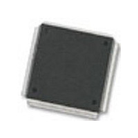
MC68376BAMFT20 Freescale Semiconductor, MC68376BAMFT20 Datasheet - Page 240

MC68376BAMFT20
Manufacturer Part Number
MC68376BAMFT20
Description
Manufacturer
Freescale Semiconductor
Datasheet
1.MC68376BAMFT20.pdf
(434 pages)
Specifications of MC68376BAMFT20
Cpu Family
68K/M683xx
Device Core
ColdFire
Device Core Size
32b
Frequency (max)
20MHz
Interface Type
QSPI/SCI
Program Memory Type
ROM
Program Memory Size
8KB
Total Internal Ram Size
7.5KB
# I/os (max)
18
Number Of Timers - General Purpose
2
Operating Supply Voltage (typ)
5V
Operating Supply Voltage (max)
5.25V
Operating Supply Voltage (min)
4.75V
On-chip Adc
16-chx10-bit
Instruction Set Architecture
RISC
Operating Temp Range
-40C to 125C
Operating Temperature Classification
Automotive
Mounting
Surface Mount
Pin Count
160
Package Type
PQFP
Lead Free Status / Rohs Status
Not Compliant
Available stocks
Company
Part Number
Manufacturer
Quantity
Price
Company:
Part Number:
MC68376BAMFT20
Manufacturer:
FREESCAL
Quantity:
245
- Current page: 240 of 434
- Download datasheet (7Mb)
11.4 A Mask Set Time Functions
11.4.1 Discrete Input/Output (DIO)
11.4.2 Input Capture/Input Transition Counter (ITC)
11-6
MOTOROLA
Arbitration is performed by means of serial assertion of IARB field bit values. The IARB
of TPUMCR is initialized to $0 during reset.
When the TPU wins arbitration, it must respond to the CPU32 interrupt acknowledge
cycle by placing an interrupt vector number on the data bus. The vector number is
used to calculate displacement into the exception vector table. Vectors are formed by
concatenating the 4-bit value of the CIBV field in TICR with the 4-bit number of the
channel requesting interrupt service. Since the CIBV field has a reset value of $0, it
must be assigned a value corresponding to the upper nibble of a block of 16 user-de-
fined vector numbers before TPU interrupts are enabled. Otherwise, a TPU interrupt
service request could cause the CPU32 to take one of the reserved vectors in the
exception vector table.
For more information about the exception vector table, refer to 4.9 Exception Pro-
cessing. Refer to 5.8 Interrupts for further information about interrupts.
The following paragraphs describe factory-programmed time functions implemented
in the A mask set TPU microcode ROM. A complete description of the functions is be-
yond the scope of this manual. Refer to the TPU Reference Manual (TPURM/AD) for
additional information.
When a pin is used as a discrete input, a parameter indicates the current input level
and the previous 15 levels of a pin. Bit 15, the most significant bit of the parameter,
indicates the most recent state. Bit 14 indicates the next most recent state, and so on.
The programmer can choose one of the three following conditions to update the pa-
rameter: 1) when a transition occurs, 2) when the CPU32 makes a request, or 3) when
a rate specified in another parameter is matched. When a pin is used as a discrete out-
put, it is set high or low only upon request by the CPU32.
Refer to TPU programming note Discrete Input/Output (DIO) TPU Function
(TPUPN18/D) for more information.
Any channel of the TPU can capture the value of a specified TCR upon the occurrence
of each transition or specified number of transitions and then generate an interrupt re-
quest to notify the CPU32. A channel can perform input captures continually, or a
channel can detect a single transition or specified number of transitions, then cease
channel activity until reinitialization. After each transition or specified number of tran-
sitions, the channel can generate a link to a sequential block of up to eight channels.
The user specifies a starting channel of the block and the number of channels within
the block. The generation of links depends on the mode of operation. In addition, after
each transition or specified number of transitions, one byte of the parameter RAM (at
an address specified by channel parameter) can be incremented and used as a flag
to notify another channel of a transition.
TIME PROCESSOR UNIT
USER’S MANUAL
MC68336/376
Related parts for MC68376BAMFT20
Image
Part Number
Description
Manufacturer
Datasheet
Request
R
Part Number:
Description:
Manufacturer:
Freescale Semiconductor, Inc
Datasheet:
Part Number:
Description:
Manufacturer:
Freescale Semiconductor, Inc
Datasheet:
Part Number:
Description:
Manufacturer:
Freescale Semiconductor, Inc
Datasheet:
Part Number:
Description:
Manufacturer:
Freescale Semiconductor, Inc
Datasheet:
Part Number:
Description:
Manufacturer:
Freescale Semiconductor, Inc
Datasheet:
Part Number:
Description:
Manufacturer:
Freescale Semiconductor, Inc
Datasheet:
Part Number:
Description:
Manufacturer:
Freescale Semiconductor, Inc
Datasheet:
Part Number:
Description:
Manufacturer:
Freescale Semiconductor, Inc
Datasheet:
Part Number:
Description:
Manufacturer:
Freescale Semiconductor, Inc
Datasheet:
Part Number:
Description:
Manufacturer:
Freescale Semiconductor, Inc
Datasheet:
Part Number:
Description:
Manufacturer:
Freescale Semiconductor, Inc
Datasheet:
Part Number:
Description:
Manufacturer:
Freescale Semiconductor, Inc
Datasheet:
Part Number:
Description:
Manufacturer:
Freescale Semiconductor, Inc
Datasheet:
Part Number:
Description:
Manufacturer:
Freescale Semiconductor, Inc
Datasheet:
Part Number:
Description:
Manufacturer:
Freescale Semiconductor, Inc
Datasheet:


