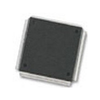
MC68376BAMFT20 Freescale Semiconductor, MC68376BAMFT20 Datasheet - Page 218

MC68376BAMFT20
Manufacturer Part Number
MC68376BAMFT20
Description
Manufacturer
Freescale Semiconductor
Datasheet
1.MC68376BAMFT20.pdf
(434 pages)
Specifications of MC68376BAMFT20
Cpu Family
68K/M683xx
Device Core
ColdFire
Device Core Size
32b
Frequency (max)
20MHz
Interface Type
QSPI/SCI
Program Memory Type
ROM
Program Memory Size
8KB
Total Internal Ram Size
7.5KB
# I/os (max)
18
Number Of Timers - General Purpose
2
Operating Supply Voltage (typ)
5V
Operating Supply Voltage (max)
5.25V
Operating Supply Voltage (min)
4.75V
On-chip Adc
16-chx10-bit
Instruction Set Architecture
RISC
Operating Temp Range
-40C to 125C
Operating Temperature Classification
Automotive
Mounting
Surface Mount
Pin Count
160
Package Type
PQFP
Lead Free Status / Rohs Status
Not Compliant
Available stocks
Company
Part Number
Manufacturer
Quantity
Price
Company:
Part Number:
MC68376BAMFT20
Manufacturer:
FREESCAL
Quantity:
245
- Current page: 218 of 434
- Download datasheet (7Mb)
10.2 Address Map
10.3 Time Base Bus System
10-2
MOTOROLA
The time base buses originate in a counter submodule and are used by the action sub-
modules. Two time base buses are accessible to each submodule.
The bus interface unit submodule (BIUSM) allows all the CTM4 submodules to pass
data to and from the IMB via the submodule bus (SMB).
The counter prescaler submodule (CPSM) generates six different clock frequencies
which can be used by any counter submodule. This submodule is contained within the
BIUSM.
The free-running counter submodule (FCSM) has a 16-bit up counter with an associ-
ated clock source selector, selectable time-base bus drivers, writable control registers,
readable status bits, and interrupt logic.The CTM4 has one FCSM.
The modulus counter submodule (MCSM) is an enhanced FCSM. A modulus register
gives the additional flexibility of recycling the counter at a count other than 64K clock
cycles. The CTM4 has two MCSMs.
The double-action submodule (DASM) provides two 16-bit input capture or two 16-bit
output compare functions that can occur automatically without software intervention.
The CTM4 has four DASMs.
The pulse width modulation submodule (PWMSM) can generate pulse width
modulated signals over a wide range of frequencies, independently of other CTM out-
put signals. PWMSMs are not affected by time base bus activity. The CTM4 has four
PWMSMs.
The CTM4 address map occupies 256 bytes from address $YFF400 to $YFF4FF. All
CTM4 registers are accessible only when the CPU32 is in supervisor mode. All re-
served addresses return zero when read, and writes have no effect. Refer to D.7 Con-
figurable Timer Module 4 for information concerning CTM4 address map and
register bit/field descriptions.
The CTM4 time base bus system is composed of three 16-bit buses: TBB1, TBB2, and
TBB4. These buses are used to transfer timing information from the counter submod-
ules to the action submodules. Two time base buses are available to each submodule.
A counter submodule can drive one of the two time base buses to which it is connect-
ed. Each action submodule can choose one of the two time base buses to which it is
connected as its time base. Control bits within each CTM4 submodule select connec-
tion to the appropriate time base bus.
The time base buses are precharge/discharge type buses with wired-OR capability.
Therefore, no hardware damage occurs when more than one counter drives the same
bus at the same time.
CONFIGURABLE TIMER MODULE 4
USER’S MANUAL
MC68336/376
Related parts for MC68376BAMFT20
Image
Part Number
Description
Manufacturer
Datasheet
Request
R
Part Number:
Description:
Manufacturer:
Freescale Semiconductor, Inc
Datasheet:
Part Number:
Description:
Manufacturer:
Freescale Semiconductor, Inc
Datasheet:
Part Number:
Description:
Manufacturer:
Freescale Semiconductor, Inc
Datasheet:
Part Number:
Description:
Manufacturer:
Freescale Semiconductor, Inc
Datasheet:
Part Number:
Description:
Manufacturer:
Freescale Semiconductor, Inc
Datasheet:
Part Number:
Description:
Manufacturer:
Freescale Semiconductor, Inc
Datasheet:
Part Number:
Description:
Manufacturer:
Freescale Semiconductor, Inc
Datasheet:
Part Number:
Description:
Manufacturer:
Freescale Semiconductor, Inc
Datasheet:
Part Number:
Description:
Manufacturer:
Freescale Semiconductor, Inc
Datasheet:
Part Number:
Description:
Manufacturer:
Freescale Semiconductor, Inc
Datasheet:
Part Number:
Description:
Manufacturer:
Freescale Semiconductor, Inc
Datasheet:
Part Number:
Description:
Manufacturer:
Freescale Semiconductor, Inc
Datasheet:
Part Number:
Description:
Manufacturer:
Freescale Semiconductor, Inc
Datasheet:
Part Number:
Description:
Manufacturer:
Freescale Semiconductor, Inc
Datasheet:
Part Number:
Description:
Manufacturer:
Freescale Semiconductor, Inc
Datasheet:


