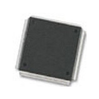
MC68376BAMFT20 Freescale Semiconductor, MC68376BAMFT20 Datasheet - Page 233

MC68376BAMFT20
Manufacturer Part Number
MC68376BAMFT20
Description
Manufacturer
Freescale Semiconductor
Datasheet
1.MC68376BAMFT20.pdf
(434 pages)
Specifications of MC68376BAMFT20
Cpu Family
68K/M683xx
Device Core
ColdFire
Device Core Size
32b
Frequency (max)
20MHz
Interface Type
QSPI/SCI
Program Memory Type
ROM
Program Memory Size
8KB
Total Internal Ram Size
7.5KB
# I/os (max)
18
Number Of Timers - General Purpose
2
Operating Supply Voltage (typ)
5V
Operating Supply Voltage (max)
5.25V
Operating Supply Voltage (min)
4.75V
On-chip Adc
16-chx10-bit
Instruction Set Architecture
RISC
Operating Temp Range
-40C to 125C
Operating Temperature Classification
Automotive
Mounting
Surface Mount
Pin Count
160
Package Type
PQFP
Lead Free Status / Rohs Status
Not Compliant
Available stocks
Company
Part Number
Manufacturer
Quantity
Price
Company:
Part Number:
MC68376BAMFT20
Manufacturer:
FREESCAL
Quantity:
245
- Current page: 233 of 434
- Download datasheet (7Mb)
10.9.9 PWM Pulse Width
10.9.10 PWM Period and Pulse Width Register Values
10.9.10.1 PWM Duty Cycle Boundary Cases
10.9.11 PWMSM Registers
MC68336/376
USER’S MANUAL
The shortest output pulse width (t
equation:
The maximum output pulse width (t
ing equation:
The value loaded into PWMA1 to obtain a given period is:
The value loaded into PWMB1 to obtain a given duty cycle is:
PWM duty cycles 0% and 100% are special boundary cases (zero pulse width and in-
finite pulse width) that are defined by the “always clear” and “always set” states of the
output flip-flop.
A zero width pulse is generated by setting PWMB2 to $0000. The output is a true
steady state signal. An infinite width pulse is generated by setting PWMB2 equal to or
greater than the period value in PWMA2. In both cases, the state of the output pin will
remain unchanged at the polarity defined by the POL bit in PWMSIC.
The PWMSM contains a status/interrupt/control register, a period register, a pulse
width register, and a counter register. All unused bits and reserved address locations
return zero when read. Writes to unused bits and reserved address locations have no
effect. The CTM4 contains four PWMSMs, each with its own set of registers. Refer to
A duty cycle of 100% is not possible when the output period is set to
65536 PWM clock periods (which occurs when PWMB2 is set to
$0000). In this case, the maximum duty cycle is 99.998% (100 x
65535/65536).
Even when the duty cycle is 0% or 100%, the PWMSM counter
continues to count.
PWMB1
t
=
PWMAX
CONFIGURABLE TIMER MODULE 4
----------------------------------
t
PWMIN
PWMA1
t
=
1
PWMIN
PWMIN
N
-------------------------------------------------------------
f
PWMAX
PWM
CLOCK
=
) that can be obtained is given by the following
=
------------------------------------ -
N
=
NOTE
CLOCK
) that can be obtained is given by the follow-
N
------------------- -
Duty Cycle %
----------------------------------- - PWMA1
CLOCK
f
f
N
sys
f
sys
sys
PERIOD
100
f
PWM
–
1
MOTOROLA
10-17
Related parts for MC68376BAMFT20
Image
Part Number
Description
Manufacturer
Datasheet
Request
R
Part Number:
Description:
Manufacturer:
Freescale Semiconductor, Inc
Datasheet:
Part Number:
Description:
Manufacturer:
Freescale Semiconductor, Inc
Datasheet:
Part Number:
Description:
Manufacturer:
Freescale Semiconductor, Inc
Datasheet:
Part Number:
Description:
Manufacturer:
Freescale Semiconductor, Inc
Datasheet:
Part Number:
Description:
Manufacturer:
Freescale Semiconductor, Inc
Datasheet:
Part Number:
Description:
Manufacturer:
Freescale Semiconductor, Inc
Datasheet:
Part Number:
Description:
Manufacturer:
Freescale Semiconductor, Inc
Datasheet:
Part Number:
Description:
Manufacturer:
Freescale Semiconductor, Inc
Datasheet:
Part Number:
Description:
Manufacturer:
Freescale Semiconductor, Inc
Datasheet:
Part Number:
Description:
Manufacturer:
Freescale Semiconductor, Inc
Datasheet:
Part Number:
Description:
Manufacturer:
Freescale Semiconductor, Inc
Datasheet:
Part Number:
Description:
Manufacturer:
Freescale Semiconductor, Inc
Datasheet:
Part Number:
Description:
Manufacturer:
Freescale Semiconductor, Inc
Datasheet:
Part Number:
Description:
Manufacturer:
Freescale Semiconductor, Inc
Datasheet:
Part Number:
Description:
Manufacturer:
Freescale Semiconductor, Inc
Datasheet:


