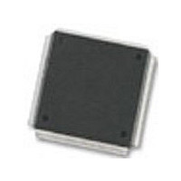
MC68376BAMFT20 Freescale Semiconductor, MC68376BAMFT20 Datasheet - Page 306

MC68376BAMFT20
Manufacturer Part Number
MC68376BAMFT20
Description
Manufacturer
Freescale Semiconductor
Datasheet
1.MC68376BAMFT20.pdf
(434 pages)
Specifications of MC68376BAMFT20
Cpu Family
68K/M683xx
Device Core
ColdFire
Device Core Size
32b
Frequency (max)
20MHz
Interface Type
QSPI/SCI
Program Memory Type
ROM
Program Memory Size
8KB
Total Internal Ram Size
7.5KB
# I/os (max)
18
Number Of Timers - General Purpose
2
Operating Supply Voltage (typ)
5V
Operating Supply Voltage (max)
5.25V
Operating Supply Voltage (min)
4.75V
On-chip Adc
16-chx10-bit
Instruction Set Architecture
RISC
Operating Temp Range
-40C to 125C
Operating Temperature Classification
Automotive
Mounting
Surface Mount
Pin Count
160
Package Type
PQFP
Lead Free Status / Rohs Status
Not Compliant
Available stocks
Company
Part Number
Manufacturer
Quantity
Price
Company:
Part Number:
MC68376BAMFT20
Manufacturer:
FREESCAL
Quantity:
245
- Current page: 306 of 434
- Download datasheet (7Mb)
A-30
MOTOROLA
Num
NOTES:
1
2
3
4
5
1. At V
2. This parameter is periodically sampled rather than 100% tested.
3. Absolute error includes 1/2 count (2.5 mV) of inherent quantization error and circuit (differential, integral, and
4. Assumes f
5. Assumes clock prescaler values of:
6. Assumes clock prescaler values of:
7. Maximum source impedance is application-dependent. Error resulting from pin leakage depends on junction
offset) error. Specification assumes that adequate low-pass filtering is present on analog input pins — capacitive
filter with 0.01
impedance of 20 k .
leakage into the pin and on leakage due to charge-sharing with internal capacitance.
Error from junction leakage is a function of external source impedance and input leakage current. In the following
expression, expected error in result value due to junction leakage is expressed in voltage (V
where I
Charge-sharing leakage is a function of input source impedance, conversion rate, change in voltage between
successive conversions, and the size of the decoupling capacitor used. Error levels are best determined
empirically. In general, continuous conversion of the same channel may not be compatible with high source
impedance.
Resolution
Differential nonlinearity
Integral nonlinearity
Absolute error
f
f
Source impedance at input
QCLK
QCLK
PQA
PQB
PQA
PQB
RH
OFF
– V
= 0.999 MHz
= 2.097 MHz
Table A-14 QADC Conversion Characteristics (Operating)
sys
QACR0: PSH = %01111, PSA = %1, PSL = 100)
CCW: BYP = %0
QACR0: PSH = %00110, PSA = %1, PSL = 010)
CCW: BYP = %0
RL
is a function of operating temperature. Refer to Table A-12.
(V
1
= 5.12 V, one count = 5 mV.
= 20.97 MHz.
DDI
2, 3, 4
F to 0.1
Parameter
and V
5
6
0.5 MHz
2
DDA
F capacitor between analog input and analog ground, typical source isolation
7
= 5.0 Vdc
ELECTRICAL CHARACTERISTICS
f
QCLK
2.1 MHz, 2 clock input sample time)
5%, V
V
Symbol
1 Count
errj
DNL
SSI
INL
AE
R
= R
S
and V
S
X I
OFF
SSA
Min
—
—
—
—
—
—
—
—
= 0 Vdc, T
Typ
A
20
—
—
—
—
—
—
5
= T
L
to T
Max
H
—
—
USER’S MANUAL
,
0.5
2.0
2.5
2.5
4.0
4.0
errj
):
MC68336/376
Counts
Counts
Counts
Unit
mV
k
Related parts for MC68376BAMFT20
Image
Part Number
Description
Manufacturer
Datasheet
Request
R
Part Number:
Description:
Manufacturer:
Freescale Semiconductor, Inc
Datasheet:
Part Number:
Description:
Manufacturer:
Freescale Semiconductor, Inc
Datasheet:
Part Number:
Description:
Manufacturer:
Freescale Semiconductor, Inc
Datasheet:
Part Number:
Description:
Manufacturer:
Freescale Semiconductor, Inc
Datasheet:
Part Number:
Description:
Manufacturer:
Freescale Semiconductor, Inc
Datasheet:
Part Number:
Description:
Manufacturer:
Freescale Semiconductor, Inc
Datasheet:
Part Number:
Description:
Manufacturer:
Freescale Semiconductor, Inc
Datasheet:
Part Number:
Description:
Manufacturer:
Freescale Semiconductor, Inc
Datasheet:
Part Number:
Description:
Manufacturer:
Freescale Semiconductor, Inc
Datasheet:
Part Number:
Description:
Manufacturer:
Freescale Semiconductor, Inc
Datasheet:
Part Number:
Description:
Manufacturer:
Freescale Semiconductor, Inc
Datasheet:
Part Number:
Description:
Manufacturer:
Freescale Semiconductor, Inc
Datasheet:
Part Number:
Description:
Manufacturer:
Freescale Semiconductor, Inc
Datasheet:
Part Number:
Description:
Manufacturer:
Freescale Semiconductor, Inc
Datasheet:
Part Number:
Description:
Manufacturer:
Freescale Semiconductor, Inc
Datasheet:


