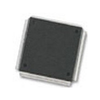
MC68376BAMFT20 Freescale Semiconductor, MC68376BAMFT20 Datasheet - Page 93

MC68376BAMFT20
Manufacturer Part Number
MC68376BAMFT20
Description
Manufacturer
Freescale Semiconductor
Datasheet
1.MC68376BAMFT20.pdf
(434 pages)
Specifications of MC68376BAMFT20
Cpu Family
68K/M683xx
Device Core
ColdFire
Device Core Size
32b
Frequency (max)
20MHz
Interface Type
QSPI/SCI
Program Memory Type
ROM
Program Memory Size
8KB
Total Internal Ram Size
7.5KB
# I/os (max)
18
Number Of Timers - General Purpose
2
Operating Supply Voltage (typ)
5V
Operating Supply Voltage (max)
5.25V
Operating Supply Voltage (min)
4.75V
On-chip Adc
16-chx10-bit
Instruction Set Architecture
RISC
Operating Temp Range
-40C to 125C
Operating Temperature Classification
Automotive
Mounting
Surface Mount
Pin Count
160
Package Type
PQFP
Lead Free Status / Rohs Status
Not Compliant
Available stocks
Company
Part Number
Manufacturer
Quantity
Price
Company:
Part Number:
MC68376BAMFT20
Manufacturer:
FREESCAL
Quantity:
245
- Current page: 93 of 434
- Download datasheet (7Mb)
5.4.3 Halt Monitor
5.4.4 Spurious Interrupt Monitor
5.4.5 Software Watchdog
MC68336/376
USER’S MANUAL
The monitor does not check DSACK response on the external bus unless the CPU32
initiates a bus cycle. The BME bit in SYPCR enables the internal bus monitor for inter-
nal to external bus cycles. If a system contains external bus masters, an external bus
monitor must be implemented and the internal-to-external bus monitor option must be
disabled.
When monitoring transfers to an 8-bit port, the bus monitor does not reset until both
byte accesses of a word transfer are completed. Monitor time-out period must be at
least twice the number of clocks that a single byte access requires.
The halt monitor responds to an assertion of the HALT signal on the internal bus,
caused by a double bus fault. A flag in the reset status register (RSR) indicates that
the last reset was caused by the halt monitor. Halt monitor reset can be inhibited by
the halt monitor (HME) enable bit in SYPCR. Refer to 5.6.5.2 Double Bus Faults for
more information.
During interrupt exception processing, the CPU32 normally acknowledges an interrupt
request, recognizes the highest priority source, and then either acquires a vector or
responds to a request for autovectoring. The spurious interrupt monitor asserts the in-
ternal bus error signal (BERR) if no interrupt arbitration occurs during interrupt
exception processing. The assertion of BERR causes the CPU32 to load the spurious
interrupt exception vector into the program counter. The spurious interrupt monitor
cannot be disabled. Refer to 5.8 Interrupts for more information. For detailed informa-
tion about interrupt exception processing, refer to 4.9 Exception Processing.
The software watchdog is controlled by the software watchdog enable (SWE) bit in
SYPCR. When enabled, the watchdog requires that a service sequence be written to
the software service register (SWSR) on a periodic basis. If servicing does not take
place, the watchdog times out and asserts the RESET signal.
Each time the service sequence is written, the software watchdog timer restarts. The
sequence to restart consists of the following steps:
1. Write $55 to SWSR.
2. Write $AA to SWSR.
BMT[1:0]
00
01
10
11
Table 5-4 Bus Monitor Period
SYSTEM INTEGRATION MODULE
Bus Monitor Time-Out Period
64 system clocks
32 system clocks
16 system clocks
8 system clocks
MOTOROLA
5-15
Related parts for MC68376BAMFT20
Image
Part Number
Description
Manufacturer
Datasheet
Request
R
Part Number:
Description:
Manufacturer:
Freescale Semiconductor, Inc
Datasheet:
Part Number:
Description:
Manufacturer:
Freescale Semiconductor, Inc
Datasheet:
Part Number:
Description:
Manufacturer:
Freescale Semiconductor, Inc
Datasheet:
Part Number:
Description:
Manufacturer:
Freescale Semiconductor, Inc
Datasheet:
Part Number:
Description:
Manufacturer:
Freescale Semiconductor, Inc
Datasheet:
Part Number:
Description:
Manufacturer:
Freescale Semiconductor, Inc
Datasheet:
Part Number:
Description:
Manufacturer:
Freescale Semiconductor, Inc
Datasheet:
Part Number:
Description:
Manufacturer:
Freescale Semiconductor, Inc
Datasheet:
Part Number:
Description:
Manufacturer:
Freescale Semiconductor, Inc
Datasheet:
Part Number:
Description:
Manufacturer:
Freescale Semiconductor, Inc
Datasheet:
Part Number:
Description:
Manufacturer:
Freescale Semiconductor, Inc
Datasheet:
Part Number:
Description:
Manufacturer:
Freescale Semiconductor, Inc
Datasheet:
Part Number:
Description:
Manufacturer:
Freescale Semiconductor, Inc
Datasheet:
Part Number:
Description:
Manufacturer:
Freescale Semiconductor, Inc
Datasheet:
Part Number:
Description:
Manufacturer:
Freescale Semiconductor, Inc
Datasheet:


