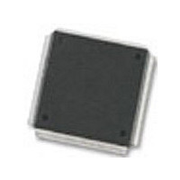
MC68376BAMFT20 Freescale Semiconductor, MC68376BAMFT20 Datasheet - Page 194

MC68376BAMFT20
Manufacturer Part Number
MC68376BAMFT20
Description
Manufacturer
Freescale Semiconductor
Datasheet
1.MC68376BAMFT20.pdf
(434 pages)
Specifications of MC68376BAMFT20
Cpu Family
68K/M683xx
Device Core
ColdFire
Device Core Size
32b
Frequency (max)
20MHz
Interface Type
QSPI/SCI
Program Memory Type
ROM
Program Memory Size
8KB
Total Internal Ram Size
7.5KB
# I/os (max)
18
Number Of Timers - General Purpose
2
Operating Supply Voltage (typ)
5V
Operating Supply Voltage (max)
5.25V
Operating Supply Voltage (min)
4.75V
On-chip Adc
16-chx10-bit
Instruction Set Architecture
RISC
Operating Temp Range
-40C to 125C
Operating Temperature Classification
Automotive
Mounting
Surface Mount
Pin Count
160
Package Type
PQFP
Lead Free Status / Rohs Status
Not Compliant
Available stocks
Company
Part Number
Manufacturer
Quantity
Price
Company:
Part Number:
MC68376BAMFT20
Manufacturer:
FREESCAL
Quantity:
245
- Current page: 194 of 434
- Download datasheet (7Mb)
8.10 Analog Input Channels
8.11 Analog Subsystem
8-12
MOTOROLA
The number of available analog channels varies, depending on whether or not exter-
nal multiplexing is used. A maximum of 16 analog channels are supported by the in-
ternal multiplexing circuitry of the converter. Table 8-2 shows the total number of
analog input channels supported with zero to four external multiplexers.
The QADC analog subsystem includes a front-end analog multiplexer, a digital to an-
alog converter (DAC) array, a comparator, and a successive approximation register
(SAR).
The analog subsystem path runs from the input pins through the input multiplexing cir-
cuitry, into the DAC array, and through the analog comparator. The output of the com-
parator feeds into the SAR and is considered the boundary between the analog and
digital subsystems of the QADC.
Figure 8-4 shows a block diagram of the QADC analog submodule.
NOTES:
No External
Mux Chips
1. The above assumes that the external trigger inputs are shared with two analog input pins.
2. When external multiplexing is used, three input channels become multiplexed address out-
puts, and for each external multiplexer chip, one input channel becomes a multiplexed ana-
log input.
16
Directly Connected + External Multiplexed = Total Channels
QUEUED ANALOG-TO-DIGITAL CONVERTER MODULE
One External
12 + 8 = 20
Mux Chip
Number of Analog Input Channels Available
Table 8-2 Analog Input Channels
Two External
11 + 16 = 27
Mux Chips
Three External
10 + 24 = 34
Mux Chips
1, 2
Four External
Mux Chips
9 + 32 = 41
USER’S MANUAL
MC68336/376
Related parts for MC68376BAMFT20
Image
Part Number
Description
Manufacturer
Datasheet
Request
R
Part Number:
Description:
Manufacturer:
Freescale Semiconductor, Inc
Datasheet:
Part Number:
Description:
Manufacturer:
Freescale Semiconductor, Inc
Datasheet:
Part Number:
Description:
Manufacturer:
Freescale Semiconductor, Inc
Datasheet:
Part Number:
Description:
Manufacturer:
Freescale Semiconductor, Inc
Datasheet:
Part Number:
Description:
Manufacturer:
Freescale Semiconductor, Inc
Datasheet:
Part Number:
Description:
Manufacturer:
Freescale Semiconductor, Inc
Datasheet:
Part Number:
Description:
Manufacturer:
Freescale Semiconductor, Inc
Datasheet:
Part Number:
Description:
Manufacturer:
Freescale Semiconductor, Inc
Datasheet:
Part Number:
Description:
Manufacturer:
Freescale Semiconductor, Inc
Datasheet:
Part Number:
Description:
Manufacturer:
Freescale Semiconductor, Inc
Datasheet:
Part Number:
Description:
Manufacturer:
Freescale Semiconductor, Inc
Datasheet:
Part Number:
Description:
Manufacturer:
Freescale Semiconductor, Inc
Datasheet:
Part Number:
Description:
Manufacturer:
Freescale Semiconductor, Inc
Datasheet:
Part Number:
Description:
Manufacturer:
Freescale Semiconductor, Inc
Datasheet:
Part Number:
Description:
Manufacturer:
Freescale Semiconductor, Inc
Datasheet:


