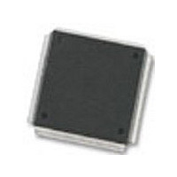
MC68376BAMFT20 Freescale Semiconductor, MC68376BAMFT20 Datasheet - Page 167

MC68376BAMFT20
Manufacturer Part Number
MC68376BAMFT20
Description
Manufacturer
Freescale Semiconductor
Datasheet
1.MC68376BAMFT20.pdf
(434 pages)
Specifications of MC68376BAMFT20
Cpu Family
68K/M683xx
Device Core
ColdFire
Device Core Size
32b
Frequency (max)
20MHz
Interface Type
QSPI/SCI
Program Memory Type
ROM
Program Memory Size
8KB
Total Internal Ram Size
7.5KB
# I/os (max)
18
Number Of Timers - General Purpose
2
Operating Supply Voltage (typ)
5V
Operating Supply Voltage (max)
5.25V
Operating Supply Voltage (min)
4.75V
On-chip Adc
16-chx10-bit
Instruction Set Architecture
RISC
Operating Temp Range
-40C to 125C
Operating Temperature Classification
Automotive
Mounting
Surface Mount
Pin Count
160
Package Type
PQFP
Lead Free Status / Rohs Status
Not Compliant
Available stocks
Company
Part Number
Manufacturer
Quantity
Price
Company:
Part Number:
MC68376BAMFT20
Manufacturer:
FREESCAL
Quantity:
245
- Current page: 167 of 434
- Download datasheet (7Mb)
MC68336/376
USER’S MANUAL
Baud rate is selected by writing a value from 2 to 255 into SPBR[7:0] in SPCR0. The
QSPI uses a modulus counter to derive SCK baud rate from the MCU system clock.
The following expressions apply to SCK baud rate:
Giving SPBR[7:0] a value of zero or one disables the baud rate generator. SCK is dis-
abled and assumes its inactive state value.
The DSCK bit in each command RAM byte inserts either a standard or user-specified
delay from chip-select assertion until the leading edge of the serial clock. The DSCKL
field in SPCR1 determines the length of the user-defined delay before the assertion of
SCK. The following expression determines the actual delay before SCK:
where DSCKL[6:0] equals {1,2,3,..., 127}.
When DSCK equals zero, DSCKL[6:0] is not used. Instead, the PCS valid-to-SCK
transition is one-half the SCK period.
There are two transfer length options. The user can choose a default value of eight
bits, or a programmed value of eight to sixteen bits, inclusive. The programmed value
must be written into BITS[3:0] in SPCR0. The BITSE bit in each command RAM byte
determines whether the default value (BITSE = 0) or the BITS value (BITSE = 1) is
used. Table 9-3 shows BITS[3:0] encoding.
SPBR[7:0]
PCS to SCK Delay
Table 9-3 Bits Per Transfer
SCK Baud Rate
BITS[3:0]
QUEUED SERIAL MODULE
0000
0001
0010
0011
0100
0101
0110
0111
1000
1001
1010
1011
1100
1101
1110
1111
=
------------------------------------------------------------------------- -
2 SCK Baud Rate Desired
Bits per Transfer
or
=
System Clock
Reserved
Reserved
Reserved
Reserved
Reserved
Reserved
Reserved
=
------------------------------------ -
2 SPBR[7:0]
System Clock
16
10
11
12
13
14
15
8
9
----------------------------------- -
System Clock
DSCKL[6:0]
MOTOROLA
9-17
Related parts for MC68376BAMFT20
Image
Part Number
Description
Manufacturer
Datasheet
Request
R
Part Number:
Description:
Manufacturer:
Freescale Semiconductor, Inc
Datasheet:
Part Number:
Description:
Manufacturer:
Freescale Semiconductor, Inc
Datasheet:
Part Number:
Description:
Manufacturer:
Freescale Semiconductor, Inc
Datasheet:
Part Number:
Description:
Manufacturer:
Freescale Semiconductor, Inc
Datasheet:
Part Number:
Description:
Manufacturer:
Freescale Semiconductor, Inc
Datasheet:
Part Number:
Description:
Manufacturer:
Freescale Semiconductor, Inc
Datasheet:
Part Number:
Description:
Manufacturer:
Freescale Semiconductor, Inc
Datasheet:
Part Number:
Description:
Manufacturer:
Freescale Semiconductor, Inc
Datasheet:
Part Number:
Description:
Manufacturer:
Freescale Semiconductor, Inc
Datasheet:
Part Number:
Description:
Manufacturer:
Freescale Semiconductor, Inc
Datasheet:
Part Number:
Description:
Manufacturer:
Freescale Semiconductor, Inc
Datasheet:
Part Number:
Description:
Manufacturer:
Freescale Semiconductor, Inc
Datasheet:
Part Number:
Description:
Manufacturer:
Freescale Semiconductor, Inc
Datasheet:
Part Number:
Description:
Manufacturer:
Freescale Semiconductor, Inc
Datasheet:
Part Number:
Description:
Manufacturer:
Freescale Semiconductor, Inc
Datasheet:


