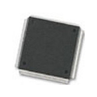
MC68376BAMFT20 Freescale Semiconductor, MC68376BAMFT20 Datasheet - Page 6

MC68376BAMFT20
Manufacturer Part Number
MC68376BAMFT20
Description
Manufacturer
Freescale Semiconductor
Datasheet
1.MC68376BAMFT20.pdf
(434 pages)
Specifications of MC68376BAMFT20
Cpu Family
68K/M683xx
Device Core
ColdFire
Device Core Size
32b
Frequency (max)
20MHz
Interface Type
QSPI/SCI
Program Memory Type
ROM
Program Memory Size
8KB
Total Internal Ram Size
7.5KB
# I/os (max)
18
Number Of Timers - General Purpose
2
Operating Supply Voltage (typ)
5V
Operating Supply Voltage (max)
5.25V
Operating Supply Voltage (min)
4.75V
On-chip Adc
16-chx10-bit
Instruction Set Architecture
RISC
Operating Temp Range
-40C to 125C
Operating Temperature Classification
Automotive
Mounting
Surface Mount
Pin Count
160
Package Type
PQFP
Lead Free Status / Rohs Status
Not Compliant
Available stocks
Company
Part Number
Manufacturer
Quantity
Price
Company:
Part Number:
MC68376BAMFT20
Manufacturer:
FREESCAL
Quantity:
245
- Current page: 6 of 434
- Download datasheet (7Mb)
Paragraph
5.6.4.2
5.6.5
5.6.5.1
5.6.5.2
5.6.5.3
5.6.5.4
5.6.6
5.6.6.1
5.7
5.7.1
5.7.2
5.7.3
5.7.3.1
5.7.3.2
5.7.3.3
5.7.4
5.7.5
5.7.5.1
5.7.5.2
5.7.6
5.7.7
5.7.8
5.7.9
5.7.10
5.8
5.8.1
5.8.2
5.8.3
5.8.4
5.8.5
5.9
5.9.1
5.9.1.1
5.9.1.2
5.9.1.3
5.9.1.4
5.9.2
5.9.3
5.9.4
5.10
5.10.1
vi
MOTOROLA
Reset ....................................................................................................... 5-40
Interrupts ................................................................................................. 5-50
Chip-Selects ............................................................................................ 5-54
Parallel Input/Output Ports ...................................................................... 5-64
Bus Exception Control Cycles ......................................................... 5-34
External Bus Arbitration ................................................................... 5-38
Reset Exception Processing ........................................................... 5-40
Reset Control Logic ......................................................................... 5-40
Reset Mode Selection ..................................................................... 5-41
MCU Module Pin Function During Reset ........................................ 5-45
Pin States During Reset .................................................................. 5-46
Reset Timing ................................................................................... 5-47
Power-On Reset .............................................................................. 5-48
Use of the Three-State Control Pin ................................................. 5-49
Reset Processing Summary ............................................................ 5-50
Reset Status Register ..................................................................... 5-50
Interrupt Exception Processing ....................................................... 5-50
Interrupt Priority and Recognition .................................................... 5-51
Interrupt Acknowledge and Arbitration ............................................ 5-52
Interrupt Processing Summary ........................................................ 5-53
Interrupt Acknowledge Bus Cycles .................................................. 5-54
Chip-Select Registers ...................................................................... 5-57
Chip-Select Operation ..................................................................... 5-60
Using Chip-Select Signals for Interrupt Acknowledge ..................... 5-61
Chip-Select Reset Operation ........................................................... 5-62
Pin Assignment Registers ............................................................... 5-64
LPSTOP Broadcast Cycle ....................................................... 5-34
Bus Errors ............................................................................... 5-36
Double Bus Faults ................................................................... 5-36
Retry Operation ....................................................................... 5-37
Halt Operation ......................................................................... 5-37
Show Cycles ........................................................................... 5-39
Data Bus Mode Selection ........................................................ 5-42
Clock Mode Selection ............................................................. 5-44
Breakpoint Mode Selection ..................................................... 5-45
Reset States of SIM Pins ........................................................ 5-46
Reset States of Pins Assigned to Other MCU Modules .......... 5-47
Chip-Select Pin Assignment Registers ................................... 5-57
Chip-Select Base Address Registers ...................................... 5-58
Chip-Select Option Registers .................................................. 5-59
Port C Data Register ............................................................... 5-60
TABLE OF CONTENTS
(Continued)
Title
USER’S MANUAL
MC68336/376
Page
Related parts for MC68376BAMFT20
Image
Part Number
Description
Manufacturer
Datasheet
Request
R
Part Number:
Description:
Manufacturer:
Freescale Semiconductor, Inc
Datasheet:
Part Number:
Description:
Manufacturer:
Freescale Semiconductor, Inc
Datasheet:
Part Number:
Description:
Manufacturer:
Freescale Semiconductor, Inc
Datasheet:
Part Number:
Description:
Manufacturer:
Freescale Semiconductor, Inc
Datasheet:
Part Number:
Description:
Manufacturer:
Freescale Semiconductor, Inc
Datasheet:
Part Number:
Description:
Manufacturer:
Freescale Semiconductor, Inc
Datasheet:
Part Number:
Description:
Manufacturer:
Freescale Semiconductor, Inc
Datasheet:
Part Number:
Description:
Manufacturer:
Freescale Semiconductor, Inc
Datasheet:
Part Number:
Description:
Manufacturer:
Freescale Semiconductor, Inc
Datasheet:
Part Number:
Description:
Manufacturer:
Freescale Semiconductor, Inc
Datasheet:
Part Number:
Description:
Manufacturer:
Freescale Semiconductor, Inc
Datasheet:
Part Number:
Description:
Manufacturer:
Freescale Semiconductor, Inc
Datasheet:
Part Number:
Description:
Manufacturer:
Freescale Semiconductor, Inc
Datasheet:
Part Number:
Description:
Manufacturer:
Freescale Semiconductor, Inc
Datasheet:
Part Number:
Description:
Manufacturer:
Freescale Semiconductor, Inc
Datasheet:


