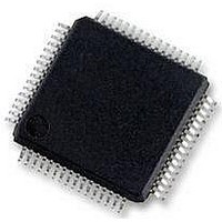
MC56F8257MLH Freescale Semiconductor, MC56F8257MLH Datasheet - Page 130

MC56F8257MLH
Manufacturer Part Number
MC56F8257MLH
Description
DSC 64K FLASH 60MHZ 64-LQFP
Manufacturer
Freescale Semiconductor
Series
56F8xxxr
Datasheets
1.TWR-56F8257.pdf
(88 pages)
2.MC56F8245VLD.pdf
(14 pages)
3.MC56F8245VLD.pdf
(2 pages)
4.MC56F8245VLD.pdf
(629 pages)
Specifications of MC56F8257MLH
Core Processor
56800E
Core Size
16-Bit
Speed
60MHz
Connectivity
CAN, I²C, LIN, SCI, SPI
Peripherals
LVD, POR, PWM, WDT
Number Of I /o
54
Program Memory Size
64KB (32K x 16)
Program Memory Type
FLASH
Ram Size
4K x 16
Voltage - Supply (vcc/vdd)
3 V ~ 3.6 V
Data Converters
A/D 16x12b, D/A 1x12b
Oscillator Type
Internal
Operating Temperature
-40°C ~ 105°C
Package / Case
64-LQFP
Product
DSCs
Processor Series
56800E
Core
56800E
Device Million Instructions Per Second
60 MIPs
Maximum Clock Frequency
60 MHz
Number Of Programmable I/os
54
Data Ram Size
8 KB
Operating Supply Voltage
3.3 V
Maximum Operating Temperature
+ 105 C
Mounting Style
SMD/SMT
Minimum Operating Temperature
- 40 C
On-chip Adc
12 bit, 8 Channel
Lead Free Status / RoHS Status
Lead free / RoHS Compliant
Eeprom Size
-
Lead Free Status / Rohs Status
Details
Available stocks
Company
Part Number
Manufacturer
Quantity
Price
Company:
Part Number:
MC56F8257MLH
Manufacturer:
MOTOLOLA
Quantity:
560
Company:
Part Number:
MC56F8257MLH
Manufacturer:
Freescale Semiconductor
Quantity:
10 000
- TWR-56F8257 PDF datasheet
- MC56F8245VLD PDF datasheet #2
- MC56F8245VLD PDF datasheet #3
- MC56F8245VLD PDF datasheet #4
- Current page: 130 of 629
- Download datasheet (4Mb)
Memory Map and Registers
130
SYNC_EN
Reserved
FORMAT
DOWN
AUTO
11–6
Field
UP
5
4
2
2
1
NOTE: Do not set CTRL[FILT_EN] when CTRL[AUTO] is 1 and CTRL[SYNC_EN] is 0. When
0
1
This read-only bitfield is reserved and always has the value zero.
Enable Up Counting
This bit enables counting up in automatic mode. See the functional description of automatic mode to
understand how this bit affects automatic waveform generation.
0
1
Enable Down Counting
This bit enables counting down in automatic mode. See the functional description of automatic mode to
understand how this bit affects automatic waveform generation.
0
1
Sync Enable
This bit enables the SYNC_IN input to be used to trigger an update of the buffered data being presented
to the analog DAC input. If CTRL[SYNC_EN] is clear, then asynchronous mode is indicated and data
written to the Buffered Data Register (DATA) will be presented to the analog DAC input in the following
IPBus clock cycle.
0
1
Automatic Mode
This bit enables automatic waveform generation mode. In automatic mode an external source (typically a
timer module) driving SYNC_IN determines the data update rate while the STEP, MINVAL, and MAXVAL
registers and CTRL[UP] and CTRL[DOWN] are used to shape the waveform. If CTRL[SYNC_EN] is not
set when using this mode, then the data for the analog DAC will be updated every clock cycle, but the
DAC output may be unable to keep up with this update rate.
0
1
Data Format
Two data formats can be used for the DAC. When this bit is clear, the 12 bits of data are right justified
within the 16 bit DATA register. When this bit is set, the 12 bits of data are left justified. In either case the
4 unused bits are ignored.
Filter disabled.
Filter enabled.
Up counting disabled.
Up counting enabled.
Down counting disabled.
Down counting enabled.
Asynchronous mode. Data written to the DATA register is presented to DAC inputs on the next clock
cycle.
Synchronous mode. A rising edge of SYNC_IN updates the data in the DATA register presented to
the DAC input.
Normal mode. Automatic waveform generation disabled.
Automatic waveform generation enabled.
CTRL[AUTO] is set and CTRL[SYNC_EN] is clear, it indicates that the data to the DAC should
be updated every clock cycle. Enabling the filter in this situation would cause the glitch filter to
filter the changes in the data being presented to the DAC and result in no change to the DAC
output.
DAC_CTRL field descriptions (continued)
MC56F825x/4x Reference Manual, Rev. 2, 10/2010
Table continues on the next page...
Preliminary
Description
Freescale Semiconductor
Related parts for MC56F8257MLH
Image
Part Number
Description
Manufacturer
Datasheet
Request
R
Part Number:
Description:
Manufacturer:
Freescale Semiconductor, Inc
Datasheet:
Part Number:
Description:
Manufacturer:
Freescale Semiconductor, Inc
Datasheet:
Part Number:
Description:
Manufacturer:
Freescale Semiconductor, Inc
Datasheet:
Part Number:
Description:
Manufacturer:
Freescale Semiconductor, Inc
Datasheet:
Part Number:
Description:
Manufacturer:
Freescale Semiconductor, Inc
Datasheet:
Part Number:
Description:
Manufacturer:
Freescale Semiconductor, Inc
Datasheet:
Part Number:
Description:
Manufacturer:
Freescale Semiconductor, Inc
Datasheet:
Part Number:
Description:
Manufacturer:
Freescale Semiconductor, Inc
Datasheet:
Part Number:
Description:
Manufacturer:
Freescale Semiconductor, Inc
Datasheet:
Part Number:
Description:
Manufacturer:
Freescale Semiconductor, Inc
Datasheet:
Part Number:
Description:
Manufacturer:
Freescale Semiconductor, Inc
Datasheet:
Part Number:
Description:
Manufacturer:
Freescale Semiconductor, Inc
Datasheet:
Part Number:
Description:
Manufacturer:
Freescale Semiconductor, Inc
Datasheet:
Part Number:
Description:
Manufacturer:
Freescale Semiconductor, Inc
Datasheet:
Part Number:
Description:
Manufacturer:
Freescale Semiconductor, Inc
Datasheet:


