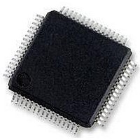
MC56F8257MLH Freescale Semiconductor, MC56F8257MLH Datasheet - Page 328

MC56F8257MLH
Manufacturer Part Number
MC56F8257MLH
Description
DSC 64K FLASH 60MHZ 64-LQFP
Manufacturer
Freescale Semiconductor
Series
56F8xxxr
Datasheets
1.TWR-56F8257.pdf
(88 pages)
2.MC56F8245VLD.pdf
(14 pages)
3.MC56F8245VLD.pdf
(2 pages)
4.MC56F8245VLD.pdf
(629 pages)
Specifications of MC56F8257MLH
Core Processor
56800E
Core Size
16-Bit
Speed
60MHz
Connectivity
CAN, I²C, LIN, SCI, SPI
Peripherals
LVD, POR, PWM, WDT
Number Of I /o
54
Program Memory Size
64KB (32K x 16)
Program Memory Type
FLASH
Ram Size
4K x 16
Voltage - Supply (vcc/vdd)
3 V ~ 3.6 V
Data Converters
A/D 16x12b, D/A 1x12b
Oscillator Type
Internal
Operating Temperature
-40°C ~ 105°C
Package / Case
64-LQFP
Product
DSCs
Processor Series
56800E
Core
56800E
Device Million Instructions Per Second
60 MIPs
Maximum Clock Frequency
60 MHz
Number Of Programmable I/os
54
Data Ram Size
8 KB
Operating Supply Voltage
3.3 V
Maximum Operating Temperature
+ 105 C
Mounting Style
SMD/SMT
Minimum Operating Temperature
- 40 C
On-chip Adc
12 bit, 8 Channel
Lead Free Status / RoHS Status
Lead free / RoHS Compliant
Eeprom Size
-
Lead Free Status / Rohs Status
Details
Available stocks
Company
Part Number
Manufacturer
Quantity
Price
Company:
Part Number:
MC56F8257MLH
Manufacturer:
MOTOLOLA
Quantity:
560
Company:
Part Number:
MC56F8257MLH
Manufacturer:
Freescale Semiconductor
Quantity:
10 000
- TWR-56F8257 PDF datasheet
- MC56F8245VLD PDF datasheet #2
- MC56F8245VLD PDF datasheet #3
- MC56F8245VLD PDF datasheet #4
- Current page: 328 of 629
- Download datasheet (4Mb)
Memory Map and Registers
10.3.5 I2C Data I/O register (I2Cx_DATA)
Addresses: I2C0_DATA – F210h base + 4h offset = F214h
328
Reset
Read
Write
Bit
Reserved
RXAK
DATA
15–8
Field
Field
7–0
0
15
0
I2C1_DATA – F220h base + 4h offset = F224h
14
0
Receive acknowledge
0
1
This read-only bitfield is reserved and always has the value zero.
Data
In master transmit mode, when data is written to this register, a data transfer is initiated. The most
significant bit is sent first. In master receive mode, reading this register initiates receiving of the next byte
of data.
NOTE: When transitioning out of master receive mode, switch the I2C mode before reading the Data
In slave mode, the same functions are available after an address match occurs.
The CR1[TX] bit must correctly reflect the desired direction of transfer in master and slave modes for the
transmission to begin. For example, if the I2C module is configured for master transmit but a master
receive is desired, then reading the Data register does not initiate the receive.
Reading the Data register returns the last byte received while the I2C module is configured in master
receive or slave receive modes. The Data register does not reflect every byte that is transmitted on the
I2C bus, and neither can software verify that a byte has been written to the Data register correctly by
reading it back.
In master transmit mode, the first byte of data written to the Data register following assertion of MST (start
bit) or assertion of RSTA (repeated start bit) is used for the address transfer and must comprise of the
calling address (in bit 7-1) concatenated with the required R/W bit (in position bit 0).
Acknowledge signal was received after the completion of one byte of data transmission on the bus
No acknowledge signal detected
13
0
register to prevent an inadvertent initiation of a master receive data transfer.
12
0
MC56F825x/4x Reference Manual, Rev. 2, 10/2010
I2Cx_SR field descriptions (continued)
0
11
0
I2Cx_DATA field descriptions
10
0
0
9
Preliminary
0
8
Description
Description
0
7
0
6
0
5
0
4
DATA
0
3
Freescale Semiconductor
0
2
0
1
0
0
Related parts for MC56F8257MLH
Image
Part Number
Description
Manufacturer
Datasheet
Request
R
Part Number:
Description:
Manufacturer:
Freescale Semiconductor, Inc
Datasheet:
Part Number:
Description:
Manufacturer:
Freescale Semiconductor, Inc
Datasheet:
Part Number:
Description:
Manufacturer:
Freescale Semiconductor, Inc
Datasheet:
Part Number:
Description:
Manufacturer:
Freescale Semiconductor, Inc
Datasheet:
Part Number:
Description:
Manufacturer:
Freescale Semiconductor, Inc
Datasheet:
Part Number:
Description:
Manufacturer:
Freescale Semiconductor, Inc
Datasheet:
Part Number:
Description:
Manufacturer:
Freescale Semiconductor, Inc
Datasheet:
Part Number:
Description:
Manufacturer:
Freescale Semiconductor, Inc
Datasheet:
Part Number:
Description:
Manufacturer:
Freescale Semiconductor, Inc
Datasheet:
Part Number:
Description:
Manufacturer:
Freescale Semiconductor, Inc
Datasheet:
Part Number:
Description:
Manufacturer:
Freescale Semiconductor, Inc
Datasheet:
Part Number:
Description:
Manufacturer:
Freescale Semiconductor, Inc
Datasheet:
Part Number:
Description:
Manufacturer:
Freescale Semiconductor, Inc
Datasheet:
Part Number:
Description:
Manufacturer:
Freescale Semiconductor, Inc
Datasheet:
Part Number:
Description:
Manufacturer:
Freescale Semiconductor, Inc
Datasheet:


