MC56F8257MLH Freescale Semiconductor, MC56F8257MLH Datasheet - Page 286
MC56F8257MLH
Manufacturer Part Number
MC56F8257MLH
Description
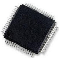
DSC 64K FLASH 60MHZ 64-LQFP
Manufacturer
Freescale Semiconductor
Series
56F8xxxr
Datasheets
1.TWR-56F8257.pdf
(88 pages)
2.MC56F8245VLD.pdf
(14 pages)
3.MC56F8245VLD.pdf
(2 pages)
4.MC56F8245VLD.pdf
(629 pages)
Specifications of MC56F8257MLH
Core Processor
56800E
Core Size
16-Bit
Speed
60MHz
Connectivity
CAN, I²C, LIN, SCI, SPI
Peripherals
LVD, POR, PWM, WDT
Number Of I /o
54
Program Memory Size
64KB (32K x 16)
Program Memory Type
FLASH
Ram Size
4K x 16
Voltage - Supply (vcc/vdd)
3 V ~ 3.6 V
Data Converters
A/D 16x12b, D/A 1x12b
Oscillator Type
Internal
Operating Temperature
-40°C ~ 105°C
Package / Case
64-LQFP
Product
DSCs
Processor Series
56800E
Core
56800E
Device Million Instructions Per Second
60 MIPs
Maximum Clock Frequency
60 MHz
Number Of Programmable I/os
54
Data Ram Size
8 KB
Operating Supply Voltage
3.3 V
Maximum Operating Temperature
+ 105 C
Mounting Style
SMD/SMT
Minimum Operating Temperature
- 40 C
On-chip Adc
12 bit, 8 Channel
Lead Free Status / RoHS Status
Lead free / RoHS Compliant
Eeprom Size
-
Lead Free Status / Rohs Status
Details
Available stocks
Company
Part Number
Manufacturer
Quantity
Price
Company:

Part Number:
MC56F8257MLH
Manufacturer:
MOTOLOLA
Quantity:
560
Company:
Part Number:
MC56F8257MLH
Manufacturer:
Freescale Semiconductor
Quantity:
10 000


Functional Description
logic which allows captures to be performed in a free running (continuous) or one shot
fashion. In free running mode, the capture sequences will be performed indefinitely. If
both capture circuits are enabled, they will work together in a ping-pong style where a
capture event from one circuit leads to the arming of the other and vice versa. In one shot
mode, only one capture sequence will be performed. If both capture circuits are enabled,
capture circuit 0 is first armed and when a capture event occurs, capture circuit 1 is
armed. Once the second capture occurs, further captures are disabled until another
capture sequence is initiated. Both capture circuits are also capable of generating an
interrupt to the CPU.
7.4.2.12 Fault Protection
Fault protection can control any combination of PWM output pins. Faults are generated
by a logic one on any of the FAULTx pins. This polarity can be changed via
FCTRL[FLVL]. Each FAULTx pin can be mapped arbitrarily to any of the PWM
outputs. When fault protection hardware disables PWM outputs, the PWM generator
continues to run, only the output pins are forced to logic 0, logic 1, or tristated depending
the values of OCTRL[PWMxFS].
The fault decoder disables PWM pins selected by the fault logic and the disable mapping
register (DISMAP). The following figure shows an example of the fault disable logic.
Each bank of bits in DISMAP control the mapping for a single PWM pin. Refer to the
following table.
The fault protection is enabled even when the PWM module is not enabled; therefore, a
fault will be latched in and must be cleared in order to prevent an interrupt when the
PWM is enabled.
MC56F825x/4x Reference Manual, Rev. 2, 10/2010
Preliminary
286
Freescale Semiconductor
Related parts for MC56F8257MLH
Image
Part Number
Description
Manufacturer
Datasheet
Request
R

Part Number:
Description:
Manufacturer:
Freescale Semiconductor, Inc
Datasheet:
Part Number:
Description:
Manufacturer:
Freescale Semiconductor, Inc
Datasheet:
Part Number:
Description:
Manufacturer:
Freescale Semiconductor, Inc
Datasheet:
Part Number:
Description:
Manufacturer:
Freescale Semiconductor, Inc
Datasheet:
Part Number:
Description:
Manufacturer:
Freescale Semiconductor, Inc
Datasheet:
Part Number:
Description:
Manufacturer:
Freescale Semiconductor, Inc
Datasheet:
Part Number:
Description:
Manufacturer:
Freescale Semiconductor, Inc
Datasheet:
Part Number:
Description:
Manufacturer:
Freescale Semiconductor, Inc
Datasheet:
Part Number:
Description:
Manufacturer:
Freescale Semiconductor, Inc
Datasheet:
Part Number:
Description:
Manufacturer:
Freescale Semiconductor, Inc
Datasheet:
Part Number:
Description:
Manufacturer:
Freescale Semiconductor, Inc
Datasheet:
Part Number:
Description:
Manufacturer:
Freescale Semiconductor, Inc
Datasheet:
Part Number:
Description:
Manufacturer:
Freescale Semiconductor, Inc
Datasheet:
Part Number:
Description:
Manufacturer:
Freescale Semiconductor, Inc
Datasheet:
Part Number:
Description:
Manufacturer:
Freescale Semiconductor, Inc
Datasheet: