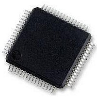
MC56F8257MLH Freescale Semiconductor, MC56F8257MLH Datasheet - Page 284

MC56F8257MLH
Manufacturer Part Number
MC56F8257MLH
Description
DSC 64K FLASH 60MHZ 64-LQFP
Manufacturer
Freescale Semiconductor
Series
56F8xxxr
Datasheets
1.TWR-56F8257.pdf
(88 pages)
2.MC56F8245VLD.pdf
(14 pages)
3.MC56F8245VLD.pdf
(2 pages)
4.MC56F8245VLD.pdf
(629 pages)
Specifications of MC56F8257MLH
Core Processor
56800E
Core Size
16-Bit
Speed
60MHz
Connectivity
CAN, I²C, LIN, SCI, SPI
Peripherals
LVD, POR, PWM, WDT
Number Of I /o
54
Program Memory Size
64KB (32K x 16)
Program Memory Type
FLASH
Ram Size
4K x 16
Voltage - Supply (vcc/vdd)
3 V ~ 3.6 V
Data Converters
A/D 16x12b, D/A 1x12b
Oscillator Type
Internal
Operating Temperature
-40°C ~ 105°C
Package / Case
64-LQFP
Product
DSCs
Processor Series
56800E
Core
56800E
Device Million Instructions Per Second
60 MIPs
Maximum Clock Frequency
60 MHz
Number Of Programmable I/os
54
Data Ram Size
8 KB
Operating Supply Voltage
3.3 V
Maximum Operating Temperature
+ 105 C
Mounting Style
SMD/SMT
Minimum Operating Temperature
- 40 C
On-chip Adc
12 bit, 8 Channel
Lead Free Status / RoHS Status
Lead free / RoHS Compliant
Eeprom Size
-
Lead Free Status / Rohs Status
Details
Available stocks
Company
Part Number
Manufacturer
Quantity
Price
Company:
Part Number:
MC56F8257MLH
Manufacturer:
MOTOLOLA
Quantity:
560
Company:
Part Number:
MC56F8257MLH
Manufacturer:
Freescale Semiconductor
Quantity:
10 000
- TWR-56F8257 PDF datasheet
- MC56F8245VLD PDF datasheet #2
- MC56F8245VLD PDF datasheet #3
- MC56F8245VLD PDF datasheet #4
- Current page: 284 of 629
- Download datasheet (4Mb)
Functional Description
7.4.2.10 Output Logic
The following figure shows the output logic of each submodule including how each
PWM output has individual fault disabling, polarity control, and output enable. This
allows for maximum flexibility when interfacing to the external circuitry.
The PWM23 and PWM45 signals which are output from the deadtime logic (refer to the
figure) are positive true signals. In other words, a high level on these signals should result
in the corresponding transistor in the PWM inverter being turned ON. The voltage level
required at the PWM output pin to turn the transistor ON or OFF is a function of the logic
between the pin and the transistor. Therefore, it is imperative that the user program
OCTRL[POLA] and OCTRL[POLB] before enabling the output pins. A fault condition
can result in the PWM output being tristated, forced to a logic 1, or forced to a logic 0
depending on the values programmed into the OCTRL[PWMxFS] fields.
7.4.2.11 E-Capture
Commensurate with the idea of controlling both edges of an output signal, the Enhanced
Capture (E-Capture) logic is designed to measure both edges of an input signal. As a
result, when a submodule pin is configured for input capture, the CVALx registers
associated with that pin are used to record the edge values.
284
from Deadtime
PWM23
PWM45
logic
Figure 7-230. Fractional Delay and Output Logic Section
PWMAFS[0]
PWMBFS[0]
Fractional
Delay 4-5
Fractional
Delay 2-3
PWMB
Disable
MC56F825x/4x Reference Manual, Rev. 2, 10/2010
Disable
PWMA
PWMAFS[1]
PWMBFS[1]
1
0
0
1
MASKB
MASKA
PWMA_EN
Preliminary
PWMB_EN
POLA
POLB
PWMA output
PWMB output
Freescale Semiconductor
Related parts for MC56F8257MLH
Image
Part Number
Description
Manufacturer
Datasheet
Request
R
Part Number:
Description:
Manufacturer:
Freescale Semiconductor, Inc
Datasheet:
Part Number:
Description:
Manufacturer:
Freescale Semiconductor, Inc
Datasheet:
Part Number:
Description:
Manufacturer:
Freescale Semiconductor, Inc
Datasheet:
Part Number:
Description:
Manufacturer:
Freescale Semiconductor, Inc
Datasheet:
Part Number:
Description:
Manufacturer:
Freescale Semiconductor, Inc
Datasheet:
Part Number:
Description:
Manufacturer:
Freescale Semiconductor, Inc
Datasheet:
Part Number:
Description:
Manufacturer:
Freescale Semiconductor, Inc
Datasheet:
Part Number:
Description:
Manufacturer:
Freescale Semiconductor, Inc
Datasheet:
Part Number:
Description:
Manufacturer:
Freescale Semiconductor, Inc
Datasheet:
Part Number:
Description:
Manufacturer:
Freescale Semiconductor, Inc
Datasheet:
Part Number:
Description:
Manufacturer:
Freescale Semiconductor, Inc
Datasheet:
Part Number:
Description:
Manufacturer:
Freescale Semiconductor, Inc
Datasheet:
Part Number:
Description:
Manufacturer:
Freescale Semiconductor, Inc
Datasheet:
Part Number:
Description:
Manufacturer:
Freescale Semiconductor, Inc
Datasheet:
Part Number:
Description:
Manufacturer:
Freescale Semiconductor, Inc
Datasheet:


