MC56F8257MLH Freescale Semiconductor, MC56F8257MLH Datasheet - Page 195
MC56F8257MLH
Manufacturer Part Number
MC56F8257MLH
Description
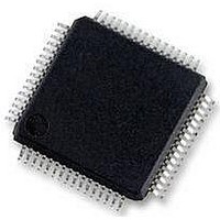
DSC 64K FLASH 60MHZ 64-LQFP
Manufacturer
Freescale Semiconductor
Series
56F8xxxr
Datasheets
1.TWR-56F8257.pdf
(88 pages)
2.MC56F8245VLD.pdf
(14 pages)
3.MC56F8245VLD.pdf
(2 pages)
4.MC56F8245VLD.pdf
(629 pages)
Specifications of MC56F8257MLH
Core Processor
56800E
Core Size
16-Bit
Speed
60MHz
Connectivity
CAN, I²C, LIN, SCI, SPI
Peripherals
LVD, POR, PWM, WDT
Number Of I /o
54
Program Memory Size
64KB (32K x 16)
Program Memory Type
FLASH
Ram Size
4K x 16
Voltage - Supply (vcc/vdd)
3 V ~ 3.6 V
Data Converters
A/D 16x12b, D/A 1x12b
Oscillator Type
Internal
Operating Temperature
-40°C ~ 105°C
Package / Case
64-LQFP
Product
DSCs
Processor Series
56800E
Core
56800E
Device Million Instructions Per Second
60 MIPs
Maximum Clock Frequency
60 MHz
Number Of Programmable I/os
54
Data Ram Size
8 KB
Operating Supply Voltage
3.3 V
Maximum Operating Temperature
+ 105 C
Mounting Style
SMD/SMT
Minimum Operating Temperature
- 40 C
On-chip Adc
12 bit, 8 Channel
Lead Free Status / RoHS Status
Lead free / RoHS Compliant
Eeprom Size
-
Lead Free Status / Rohs Status
Details
Available stocks
Company
Part Number
Manufacturer
Quantity
Price
Company:

Part Number:
MC56F8257MLH
Manufacturer:
MOTOLOLA
Quantity:
560
Company:
Part Number:
MC56F8257MLH
Manufacturer:
Freescale Semiconductor
Quantity:
10 000


7.2.7 PWM[n]_EXTA and PWM[n]_EXTB - Alternate PWM Control
These pins allow an alternate source to control the PWMA and PWMB outputs.
Typically, either the EXTA or EXTB input (depending on the state of MCTRL[IPOL]) is
used for the generation of a complementary pair. Typical control signals include ADC
conversion high/low limits, TMR outputs, GPIO inputs, and comparator outputs.
On the MC56F825x/MC56F824x:
7.2.8 PWM[n]_OUT_TRIG0 and PWM[n]_OUT_TRIG1 - Output
These outputs allow the PWM submodules to control timing of ADC conversions. See
the description of the Output Trigger Control Register for information about how to
enable these outputs and how the compare registers match up to the output triggers.
7.2.9 EXT_CLK - External Clock Signal
This on-chip input signal allows an on-chip source external to the PWM (typically a
timer) to control the PWM clocking. In this manner, the PWM can be synchronized to the
on-chip source. This signal must be generated synchronously to the PWM's clock because
it is not resynchronized in the PWM.
Freescale Semiconductor
• PWM0_EXTA to PWM3_EXTA are connected to crossbar outputs XBAR_OUT12
• PWM0_EXTB connects to ADC sample 0's high/low limit flag. This flag is cleared
• PWM1_EXTB connects to ADC sample 1's high/low limit flag. This flag is cleared
• PWM2_EXTB connects to ADC sample 2's high/low limit flag. This flag is cleared
• PWM3_EXTB is connected to ground.
to XBAR_OUT15.
when the ADC conversion result is higher than the value programmed into the ADC
High Limit Register 0, and the flag is set when the ADC conversion result is lower
than the value programmed into the ADC Low Limit Register 0.
when the ADC conversion result is higher than the value programmed into the ADC
High Limit Register 1, and the flag is set when the ADC conversion result is lower
than the value programmed into the ADC Low Limit Register 1.
when the ADC conversion result is higher than the value programmed into the ADC
High Limit Register 2, and the flag is set when the ADC conversion result is lower
than the value programmed into the ADC Low Limit Register 2.
Signals
Triggers
MC56F825x/4x Reference Manual, Rev. 2, 10/2010
Preliminary
Chapter 7 Enhanced Flex Pulse Width Modulator (eFlexPWM)
195
Related parts for MC56F8257MLH
Image
Part Number
Description
Manufacturer
Datasheet
Request
R

Part Number:
Description:
Manufacturer:
Freescale Semiconductor, Inc
Datasheet:
Part Number:
Description:
Manufacturer:
Freescale Semiconductor, Inc
Datasheet:
Part Number:
Description:
Manufacturer:
Freescale Semiconductor, Inc
Datasheet:
Part Number:
Description:
Manufacturer:
Freescale Semiconductor, Inc
Datasheet:
Part Number:
Description:
Manufacturer:
Freescale Semiconductor, Inc
Datasheet:
Part Number:
Description:
Manufacturer:
Freescale Semiconductor, Inc
Datasheet:
Part Number:
Description:
Manufacturer:
Freescale Semiconductor, Inc
Datasheet:
Part Number:
Description:
Manufacturer:
Freescale Semiconductor, Inc
Datasheet:
Part Number:
Description:
Manufacturer:
Freescale Semiconductor, Inc
Datasheet:
Part Number:
Description:
Manufacturer:
Freescale Semiconductor, Inc
Datasheet:
Part Number:
Description:
Manufacturer:
Freescale Semiconductor, Inc
Datasheet:
Part Number:
Description:
Manufacturer:
Freescale Semiconductor, Inc
Datasheet:
Part Number:
Description:
Manufacturer:
Freescale Semiconductor, Inc
Datasheet:
Part Number:
Description:
Manufacturer:
Freescale Semiconductor, Inc
Datasheet:
Part Number:
Description:
Manufacturer:
Freescale Semiconductor, Inc
Datasheet: