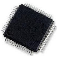
MC56F8257MLH Freescale Semiconductor, MC56F8257MLH Datasheet - Page 285

MC56F8257MLH
Manufacturer Part Number
MC56F8257MLH
Description
DSC 64K FLASH 60MHZ 64-LQFP
Manufacturer
Freescale Semiconductor
Series
56F8xxxr
Datasheets
1.TWR-56F8257.pdf
(88 pages)
2.MC56F8245VLD.pdf
(14 pages)
3.MC56F8245VLD.pdf
(2 pages)
4.MC56F8245VLD.pdf
(629 pages)
Specifications of MC56F8257MLH
Core Processor
56800E
Core Size
16-Bit
Speed
60MHz
Connectivity
CAN, I²C, LIN, SCI, SPI
Peripherals
LVD, POR, PWM, WDT
Number Of I /o
54
Program Memory Size
64KB (32K x 16)
Program Memory Type
FLASH
Ram Size
4K x 16
Voltage - Supply (vcc/vdd)
3 V ~ 3.6 V
Data Converters
A/D 16x12b, D/A 1x12b
Oscillator Type
Internal
Operating Temperature
-40°C ~ 105°C
Package / Case
64-LQFP
Product
DSCs
Processor Series
56800E
Core
56800E
Device Million Instructions Per Second
60 MIPs
Maximum Clock Frequency
60 MHz
Number Of Programmable I/os
54
Data Ram Size
8 KB
Operating Supply Voltage
3.3 V
Maximum Operating Temperature
+ 105 C
Mounting Style
SMD/SMT
Minimum Operating Temperature
- 40 C
On-chip Adc
12 bit, 8 Channel
Lead Free Status / RoHS Status
Lead free / RoHS Compliant
Eeprom Size
-
Lead Free Status / Rohs Status
Details
Available stocks
Company
Part Number
Manufacturer
Quantity
Price
Company:
Part Number:
MC56F8257MLH
Manufacturer:
MOTOLOLA
Quantity:
560
Company:
Part Number:
MC56F8257MLH
Manufacturer:
Freescale Semiconductor
Quantity:
10 000
- TWR-56F8257 PDF datasheet
- MC56F8245VLD PDF datasheet #2
- MC56F8245VLD PDF datasheet #3
- MC56F8245VLD PDF datasheet #4
- Current page: 285 of 629
- Download datasheet (4Mb)
The following figure is a block diagram of the E-Capture circuit. Upon entering the pin
input, the signal is split into two paths. One goes straight to a mux input where software
can select to pass the signal directly to the capture logic for processing. The other path
connects the signal to an 8 bit counter which counts both the rising and falling edges of
the signal. The output of this counter is compared to an 8 bit value that is specified by the
user (EDGCMPx) and when the two values are equal, the comparator generates a pulse
that resets the counter. This pulse is also supplied to the mux input where software can
select it to be processed by the capture logic. This feature permits the E-Capture circuit to
count up to 256 edge events before initiating a capture event. this feature is useful for
dividing down high frequency signals for capture processing so that capture interrupts
don't overwhelm the CPU. Also, this feature can be used to simply generate an interrupt
after "n" events have been counted.
Based on the mode selection, the mux selects either the pin input or the compare output
from the count/compare circuit to be processed by the capture logic. The selected signal
is routed to two separate capture circuits which work in tandem to capture sequential
edges of the signal. The type of edge to be captured by each circuit is determined by
CAPTCTRLx[EDGx1] and CAPTCTRLx[EDGx0], whose functionality is listed in the
preceding figure. Also, controlling the operation of the capture circuits is the arming
Freescale Semiconductor
Pin Input
EDGCNT_EN
This logic is repeated for
PWMA, PWMB, and PWMX
inputs.
EDGCMP
counter
8 bit
Figure 7-231. Enhanced Capture (E-Capture) Logic
EDGCNT
MC56F825x/4x Reference Manual, Rev. 2, 10/2010
reset
00 - Disabled
01 - Capture falling edges
10 - Capture rising edges
11 - Capture any edge
EDGx bits
INP_SEL
Submodule
Timer
Preliminary
Chapter 7 Enhanced Flex Pulse Width Modulator (eFlexPWM)
0
1
Circuit 0
Circuit 1
Capture
Capture
Arming
Logic
CIE0
CF0
CIE1
CF1
EDG0
EDG1
Int
Int
285
Related parts for MC56F8257MLH
Image
Part Number
Description
Manufacturer
Datasheet
Request
R
Part Number:
Description:
Manufacturer:
Freescale Semiconductor, Inc
Datasheet:
Part Number:
Description:
Manufacturer:
Freescale Semiconductor, Inc
Datasheet:
Part Number:
Description:
Manufacturer:
Freescale Semiconductor, Inc
Datasheet:
Part Number:
Description:
Manufacturer:
Freescale Semiconductor, Inc
Datasheet:
Part Number:
Description:
Manufacturer:
Freescale Semiconductor, Inc
Datasheet:
Part Number:
Description:
Manufacturer:
Freescale Semiconductor, Inc
Datasheet:
Part Number:
Description:
Manufacturer:
Freescale Semiconductor, Inc
Datasheet:
Part Number:
Description:
Manufacturer:
Freescale Semiconductor, Inc
Datasheet:
Part Number:
Description:
Manufacturer:
Freescale Semiconductor, Inc
Datasheet:
Part Number:
Description:
Manufacturer:
Freescale Semiconductor, Inc
Datasheet:
Part Number:
Description:
Manufacturer:
Freescale Semiconductor, Inc
Datasheet:
Part Number:
Description:
Manufacturer:
Freescale Semiconductor, Inc
Datasheet:
Part Number:
Description:
Manufacturer:
Freescale Semiconductor, Inc
Datasheet:
Part Number:
Description:
Manufacturer:
Freescale Semiconductor, Inc
Datasheet:
Part Number:
Description:
Manufacturer:
Freescale Semiconductor, Inc
Datasheet:


